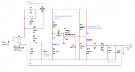
looking for a BJT buffer to follow the Fetzer Valve Revisited possibly like this emitter follower
i understand some basics of transistors but i could use some help.
Does Q1 need a bias resistor from gate to V+ ? (the Fetzer design does not use one)
Q1 Zout seems to be 14k according to Multisim. is the volume pot in the best place, impedance wise?
the pot wiper position seems to change the voltage at the output of Q1 (loading). i could eliminate C4 if i knew & can count on the voltage at Q2 to be steady. otherwise i have to bias it, is this correct?
any way to make this simple 2-stage amp more elegant?
any other suggestions are welcome! thanks.
i am still getting strange interactions between the 2 stages although they simulate fine separately. and now i see a half-wave rectified type of output on the scope.
i have tried removing R6 pot & C9 coupling cap (and rebiasing), no help there.
Reducing emitter resistor R15 to 10k makes things even worse, creates a strong LPF at about 1kHz.
I am new to transistors and am just trying to add a low Z buffer to the Fetzer stage. I am lost..
any advice is really appreciated!!
Attachments
thank you Loud, i have added coupling caps and voltage probe points.
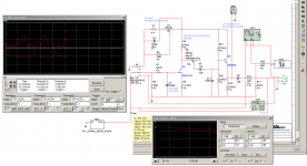
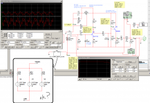
when i reduce R15 to say 10k, i get a full waveform on the scope. but the Bode plotter then shows a huge frequency dip -10dB centered around 4500Hz, i can't find where this filter action is happpening. when i looked at either transistor stage alone, they seemed to be ok, not totally sure about this tho.
Note that I chose the 4117 FET based on desired specs for Idss and Vp specs according to the Fetzer Revisited article. I am not sure if I should take more gain in this stage, however (or how to do it). I would like to design for a volume range from pristine clean tone with maximum headroom, to a slight overdrive, if possible. I want a Zout of 600-1k after the emitter follower for plugging into a console/audio interface. I am open to changing anything you see. Thanks so much for taking a look.
Attachments
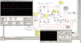
this shows what happens when i change the pot to a rheostat type of style, and change emitter resistor R15 to 10k (approx. 1/10th of the R21 || R22 which i think is more textbook)
is the pot even in the best location? considering i want very low Zout, i thought this was the best place for it instead of at end of circuit. if i could have something like a ~5k pot on the very output, then that would also get my output impedance within spec, since the Zout of the pot would be 0-1250 ohms max. even this is higher than i had hoped for though.
is the pot even in the best location? considering i want very low Zout, i thought this was the best place for it instead of at end of circuit. if i could have something like a ~5k pot on the very output, then that would also get my output impedance within spec, since the Zout of the pot would be 0-1250 ohms max. even this is higher than i had hoped for though.
Attachments
GOT IT
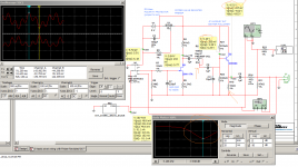
now THIS is what i am talking about!")
the Multisim impedance meter (with the recommended 50ohm input resis) was causing that huge drop in level in the high freq's. makes sense, a 50ohm load just doesn't sound right at all.
i also temporarily got rid of the volume pot and biasing resistors for the EF and everything seems to be fitting into place now. very encouraging.
now, how do get the volume range i would like (clean/max headroom to slightly overdriven. slightly overdriven (driving a console input) is what, maybe 2-3V pk-pk? i probably need a better guitar circuit model (see inset) to start with. mine is a guess.
and then, to find the best place for the volume pot. i am also considering adding a passive 2-pot tone circuit between the 2 transistor stages.
thanks, hope this thread helps someone else too.
now THIS is what i am talking about!
the Multisim impedance meter (with the recommended 50ohm input resis) was causing that huge drop in level in the high freq's. makes sense, a 50ohm load just doesn't sound right at all.
i also temporarily got rid of the volume pot and biasing resistors for the EF and everything seems to be fitting into place now. very encouraging.
now, how do get the volume range i would like (clean/max headroom to slightly overdriven. slightly overdriven (driving a console input) is what, maybe 2-3V pk-pk? i probably need a better guitar circuit model (see inset) to start with. mine is a guess.
and then, to find the best place for the volume pot. i am also considering adding a passive 2-pot tone circuit between the 2 transistor stages.
thanks, hope this thread helps someone else too.
Attachments
Enhancements for the "emitter follower for onboard guitar preamp".
Hi n0nspaz,
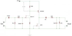
I attached a jpg schematic of your design with some suggestions that will fix some of the biasing issues you mentioned and improve the gain of Q1. Please let me know if this was helpful and/or if you have any questions.
Good Luck, JP
Hi n0nspaz,
I attached a jpg schematic of your design with some suggestions that will fix some of the biasing issues you mentioned and improve the gain of Q1. Please let me know if this was helpful and/or if you have any questions.
Good Luck, JP
Attachments
Hi n0nspaz,
I attached a jpg schematic of your design with some suggestions that will fix some of the biasing issues you mentioned and improve the gain of Q1. Please let me know if this was helpful and/or if you have any questions.
Good Luck, JP
Thanks so much JP. can you help with my goals?
- passive & active use of the Strat via push/pull pot, active out is in phase with passive
- final Zout of the circuit <1k - to interface with a console/audio interface
- EQ with mid boost & cut, LPF & HPF -this is another circuit and another topic, not sure active or passive
- switchable diode clipper
i am thinking 6-12dB of gain upfront should be plenty.
Fetzer Valve Revisited at the bottom of the page has a Rd and Rs FET resistor calculator that I was blindly following. Will your R4 reduce my input headroom?
trying to insert a passive EQ circuit after the vol pot now.
although the 2N4117 uses VERY low battery power i am thinking of using an NTE457 (Vp 1.26, Idss 1.09mA) instead. this will give me a Zout (R4 in your schematic) of 5.3k according to the Fetzer calc. thus my vol pot can be 10k or 25k, reducing noise and allowing a passive EQ using reasonable Zin, to follow it. still drawing this up.
love to hear your thoughts! thanks again!
i had the idea of switching in C14 to make up for the passive EQ loss (when EQ is engaged). maybe i should just put a state variable in there. if anyone knows of a small footprint EQ that will give me HPF, LPF, wide mid scoop 'acoustic' guitar sound, and modest mid boost (Clapton or whatever)...this is what i am after. what you see is the closest i have come.
challenges:
1. circuit inverts signal polarity
2. EQ is done by brute force modelling and none of this is tested yet in the real world
cheers
challenges:
1. circuit inverts signal polarity
2. EQ is done by brute force modelling and none of this is tested yet in the real world
cheers
Attachments
More mods based on your requirements.
Hi nOnspaz,
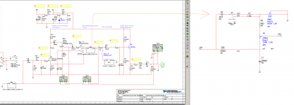
I attached a schematic of suggested mods to your original preamp design. I recommend that you keep the original JFET front end but to achieve low-Z drive (into 10kOhm) and stay in-phase with your passive signal chain, I would suggest using an inverting opamp stage as described in the schematic.
I like your ideas about cut-and-boost and diode-clipping circuits but I would suggest using an active circuit for those applications. There are some pretty cool tone circuits that are passive (e.g. the original Donahue Tele passive) but you get many more options when you go active.
Please let me know your thoughts. JP
Hi nOnspaz,
I attached a schematic of suggested mods to your original preamp design. I recommend that you keep the original JFET front end but to achieve low-Z drive (into 10kOhm) and stay in-phase with your passive signal chain, I would suggest using an inverting opamp stage as described in the schematic.
I like your ideas about cut-and-boost and diode-clipping circuits but I would suggest using an active circuit for those applications. There are some pretty cool tone circuits that are passive (e.g. the original Donahue Tele passive) but you get many more options when you go active.
Please let me know your thoughts. JP
Attachments
Please note that on the last schematic post (nOnspaz_lowZ_driver.pdf), R2 is an 11.3K Ohm resistor and not an 11.3 Ohm resistor. In addition, check to make sure J1 is biased correctly by measuring the DC voltage at the Drain of J1; it should be between 1/2 and 2/3 V1 (9 volt battery).
JP
JP
Hi
The 4117 J-fets I use in my projects have Idss from 40-60uA. So a class A bias of 20uA is reasonable, could even be more like 15uA. Expect Vgs @ 20uA to be around -0.2V so 11K for the source resistor should be fairly close. Because of the variance in J-fets, this resistor value may need some small adjustments.
Add too many caps and filters to such a high impedance circuit, in the real world, and you might end up with a radio reciever.
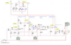
J-fets are well suited for direct coupling to BJT's. Why capacitor couple the J-fet to the BJT? In this similar circuit I just made up, the drain resistor drops 4V resulting in 4.6Vce on the 5089. The 5089 transistors I have, has a current gain of about 500. J202 Idss is about 2 or 3mA. 3mA/500=6uA, so the drain resistor would be 4V/(20uA + 6uA)= 153.8K or 150K. For 15uA Id, 4V/(15uA + 6uA)= 190K.
The 4117 J-fets I use in my projects have Idss from 40-60uA. So a class A bias of 20uA is reasonable, could even be more like 15uA. Expect Vgs @ 20uA to be around -0.2V so 11K for the source resistor should be fairly close. Because of the variance in J-fets, this resistor value may need some small adjustments.
Add too many caps and filters to such a high impedance circuit, in the real world
, and you might end up with a radio reciever.J-fets are well suited for direct coupling to BJT's. Why capacitor couple the J-fet to the BJT? In this similar circuit I just made up, the drain resistor drops 4V resulting in 4.6Vce on the 5089. The 5089 transistors I have, has a current gain of about 500. J202 Idss is about 2 or 3mA. 3mA/500=6uA, so the drain resistor would be 4V/(20uA + 6uA)= 153.8K or 150K. For 15uA Id, 4V/(15uA + 6uA)= 190K.
Attachments
Last edited:
Hi CBS240,
I agree, I like your design for it's elegance (without the coupling cap), very cool. The only reason I would suggest the more complex coupling cap and extra biasing resistor(s) configuration would be due to the slight variance in biasing parameters for the average JFET. Unless you predetermine what those biasing levels would be, you might have a symmetry issue with the output biasing point of the emitter follower stage. Probably not an issue for this application though. Simpler is almost always better. Thanks, JP
I agree, I like your design for it's elegance (without the coupling cap), very cool. The only reason I would suggest the more complex coupling cap and extra biasing resistor(s) configuration would be due to the slight variance in biasing parameters for the average JFET. Unless you predetermine what those biasing levels would be, you might have a symmetry issue with the output biasing point of the emitter follower stage. Probably not an issue for this application though. Simpler is almost always better. Thanks, JP
the challenge is keeping the footprint as small as possible since the idea is to build it into the body of a strat.
since i use a fixed bridge, not tremolo, i plan to mount the 9V battery in the rear bridge compartment and the circuitry in the pot/switch cavity, somehow.
that's why i was thinking of using the Orman AMZ tone control (big muff modified tone control). but then i wanted a mid boost as well as scoop and i went off the deep end...now considering active EQ lol
fact is, small footprint is big here.
is it possible: Fetzer preamp + EQ + simple diode clip + Zout <1k
with:
- noninverted signal at output (in any switched position)
- using transistors, not opamps if possible (just because i want to learn more about them)
thank you guys
cheers
so JP, if i measure the actual Idss and Vp (pinch-off) of the exact transistor i am using, which i am doing using the circuit at the bottom of the Fetzer Valve Revisited page, are there caps or resistors that can be eliminated from the circuit?
i am new to transistor circuits (but am famil with opamps) so i apologize if some of this really basic.
other curiosities:
1. How do the 4117 & 4118 draw such low current but provide so much gain? what is the catch? it does have a high Zout. but does it sound nasty or something?
2. i am thinking of switching to an NTE457 for lower Zout, which will allow me a smaller series volume pot before the EQ (less noise?). do you guys think this is wise?
3. is there a noninverting buffer with Zout of <1k using a transistor?
here is my latest attempt
1. i moved the GreenBean Buffer biasing resistors to the 'power supply'. is it ok to create a Vb like this and bias the 2 emitter followers like so, or do they need dedicated resistor dividers for each tranny? also- how do i know these values are what i need. do i calculate current flow for ~1mA per tranny? i am new to transistors.
2. is this the best place for the volume pot?
3. i am still seeing loading effects on the passive EQ circuit (The New AMZ Tone Control) I am trying to isolate each section with caps, etc. but i must be missing something.
thanks
hope this helps others too.
Attachments
- Status
- This old topic is closed. If you want to reopen this topic, contact a moderator using the "Report Post" button.
- Home
- Live Sound
- Instruments and Amps
- emitter follower for onboard guitar preamp