My 5E3 Tweed Deluxe build
I designed a circuit board of my own based on the Fender 5E3 schematic. I fire it up and get no DC to the power rail. The 5Y3GT is wired thusly - pins 4 and 6 each get a red lead and show a nice sine wave and carry 350VAC. Pin 2 has a single yellow lead. Pin 8 has a yellow lead, the red OT lead, and the cap and resistor. Red/yellow lead is tied to ground. Ground net of the circuit board is tied to same point. Heater circuit is good.
Pin 8 net reads 4.6VAC. No DC at all. I've swapped the yellow leads to no avail. Want to seek advice before I cut and jump too much.
Any suggestions for me to try? Already bought a new JJ tube in case my original was bad.
Last edited:
I don't know what you're doing here exactly, but if you were going to use a power transformer with no centre tap then what you would need is a Hybrid Bridge. For this you take a pair of UF4007 diodes and connect them between the two high voltage AC inputs to your rectifier and your ground. The lines round the diodes point to the tube pins and away from ground, as shown in the hybrid bridge diagram.
BUT!! With your transformer this will give you 350v x 1.4 or approx 490v. So DO NOT DO THIS with a 350v AC transformer!!!
The 5E3 circuit expects a HT of 375v as far as I can see, so for a hybrid bridge this is the WRONG value transformer. You'd be wanting a mains transformer with an output of around 285v AC, and of course the right current rating. If you used 350v AC it would be altogether too high for your circuit and the tube and capacitor ratings - totally unsafe, so don't try it!
See diagram in post 12 below for a hybrid bridge
http://www.audiokarma.org/forums/showthread.php?t=445418
I'm getting 375v from the 5E3 schematic here:
http://www.lindonstonemusic.ca/schematics/fender/fender-deluxe-5e3.gif
Last edited:
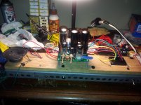
Thanks for the responses. Here is my schematic and more information. Can anything be determined from it?
The two xfmrs are Hammond replacements for the Tweed Deluxe, models 290AX and 1750H so there should be no problem with them. The red/yel center tap now goes to AC input chassis GND. I originally had it soldered to GND mecca on my board, which is E16, right next to the switch on the schematic. The *board* (at E16) is grounded now with a wire that also attaches to the same place as the red/yel lead, so I really didn't change much. My prototype has no Standby Switch installed. Also the two diodes by the 5Y3GT are *not* installed. I'm not sure why they were there in the first place, as I was adopting someone else's idea. I'm not an EE, I'm a pcb designer, so I know just enough to get myself into trouble
The two xfmrs are Hammond replacements for the Tweed Deluxe, models 290AX and 1750H so there should be no problem with them. The red/yel center tap now goes to AC input chassis GND. I originally had it soldered to GND mecca on my board, which is E16, right next to the switch on the schematic. The *board* (at E16) is grounded now with a wire that also attaches to the same place as the red/yel lead, so I really didn't change much. My prototype has no Standby Switch installed. Also the two diodes by the 5Y3GT are *not* installed. I'm not sure why they were there in the first place, as I was adopting someone else's idea. I'm not an EE, I'm a pcb designer, so I know just enough to get myself into trouble
Attachments
You also have to wait for the tube to warm up right?
Sir, how long does that take? I'm not a musician either!
Since you mentioned correct vac readings, and it does read as if the 5y3 is wired correctly, two questions. 1 is the tube warming up (filament glowing)? want to make sure the tube is good, and 2, are you reading for vdc from pin 8 to ground with a vac scale on meter instead of a vdc scale? I have made the mistake of doing various readings and forgetting to change the meter setting.
Make sure D1 and D2 are installed in the correct orientation, banded ends facing towards pins 4 & 6.. Check for obvious miswiring, I will confess that on more than one occasion I have wired an ENTIRE socket backwards!
Verify the filament is glowing, it should only take a few seconds for the 5Y3 filament to start to light up.
You can verify the filament continuity with a DMM, you should be able to measure a few ohms or less between the filament pins.
I've seen some weird stuff in guitar amplifiers, but pins 2 & 3 of the volume control appear to be swapped. (Or not, would need to see the original to be sure that is not the case. It'll work either way.)
The input pot you deleted is not strictly necessary since most guitars have a volume pot.
 Also since this is obviously a guitar amplifier it belongs in the Instruments & Amplifier forum. See the subtitle line above each forum for the reason why.
Um, if the problem is missing high voltage DC, then wiring the preamp is irrelevant. Fix that after the power is restored. Same with grounding. It matters for hum reasons where the power transformer center tap is grounded, but in terms of just getting the DC voltage, you should get something there if the CT is grounded anywhere.
If the rectifier tube heaters are not glowing, that is the problem.
Those extra diodes are there for protection, you can leave them out and the amp should still function. If you have them and they are backwards, you will get no high voltage DC.
If the rectifier tube heaters are not glowing, that is the problem.
Those extra diodes are there for protection, you can leave them out and the amp should still function. If you have them and they are backwards, you will get no high voltage DC.
I'll get to the point quickly - I installed three tube sockets improperly on my board, turned one pin from how they should have been. Sigh...that's me. So I'm going to fix it the right way and re-solder them. I owe everyone who responded a lot of thanks, and also a report on the success or failure of my amp when I fix my screw ups. That should be soon...
The schematic shows R22 and R12 in parallel, each 250 ohms. For 6V6 tubes there should only be one 250 (or higher) resistor. Some builders find 270 ohms controls bias better but it depends on the tubes used and B+ value.
Loudthud, Thanks for the info. Here's what I did. I had space problems on the board. Couldn't find a place for that big resistor. So I split it in two and gave each 6V6 its own return. I realized later (like after I bought 2 bare boards) that maybe the 6V6's do need to be attached between their pin 8's. I jumped them together so now the R's are sorta redundant, but should carry all the current.
- Status
- This old topic is closed. If you want to reopen this topic, contact a moderator using the "Report Post" button.
- Home
- Live Sound
- Instruments and Amps
- 5Y3GT rectifier difficulty