I have a Marshall AVT50 that keeps blowing fuses. I unplugged the leads to the TDA7293 board, and the fuse does not blow, but I removed that board and inspected it very carefully, and I can't find any sign of abuse, heat, or other distress. It looks new.
Should I replace the TDA7293 chip anyway, or can I test it first? Do they sell some that don't have the mute function, or will I be ok as long as the chip is a TDA7293?
Is there a cheap place to get these fuses?
Thanks.
Should I replace the TDA7293 chip anyway, or can I test it first? Do they sell some that don't have the mute function, or will I be ok as long as the chip is a TDA7293?
Is there a cheap place to get these fuses?
Thanks.
The power supply pins to ground and the output pin as well.
if any of these combinations show a dead short then the chip is bad.
VS2000 AVT 150h, replacing TDA7293 w/ pics & schematics - Marshall Amp Forum
tda7293 marshall - Google Search
No,you don't have to remove the chip from the board to do this test.
jer")
if any of these combinations show a dead short then the chip is bad.
VS2000 AVT 150h, replacing TDA7293 w/ pics & schematics - Marshall Amp Forum
tda7293 marshall - Google Search
No,you don't have to remove the chip from the board to do this test.
jer
Last edited:
Sounds like it is shorted to me !!
I have a friend that has one of those amps and he just had the power amp chips replaced.
And it is now working fine.
I didn't do the repair on it but I good friend of mine did as he does this stuff in my area.
We are not exactly sure of the cause but I guess it happens quite often as he keeps these chips in stock.
jer
Hey, do you know what kind of stuff Marshall put between the chip and the metal plate? It seems to have been some kind of adhesive, and it doesn't look at all like the white conductive heat sink stuff I'm used to using.
Some thread said the chip needed to be insulated from the metal plate, but I think the plate helps cool the chip. Is the adhesive some kind of special thermally conductive, but non electrically conductive stuff?
Thanks. Don't want to overheat or short the new one.
Some thread said the chip needed to be insulated from the metal plate, but I think the plate helps cool the chip. Is the adhesive some kind of special thermally conductive, but non electrically conductive stuff?
Thanks. Don't want to overheat or short the new one.
Can you post a picture of it?
I have never taken one of those apart.
They do make such compounds.
You can get electrically insulated thermal pads and just cut them to size.
Or get one that is made for that size of chip.
Or you can make one out of some very thin Mylar or kapton.
The last time I repaired one of my amps with some 2N3055's I used some mylar and it worked great as the mica ones I had where all broken up.
Some of those chips are insulated but I am not sure about the TDA7293.
You will have to check the data sheet on that one,or ,look through the chipamp forum someone there would know right off of the bat as if they are insulated or not.
If you can peel it off the original pad with out destroying it you can reuse it or if it is still stuck to the heatsink and not the chip then put some compound on the new chip and mount it.
Many heatsink compounds do dry up and give the appeal as if they were some kind of adhesive as well after time.
Check with your vendor when you get the new chip as they should have many types of insulators in stock.
here are a couple of examples of different pad styles,
http://www.tdpri.com/forum/1914449-post15.html
http://music-electronics-forum.com/attachments/6013d1250711463-p1030264.jpg
Make sure that you include any nylon or plastic insulating washers when you remount the chip as well !
Here is a link to some pad material,
http://www.digikey.com/product-search/en/fans-thermal-management/thermal-pads-sheets/1179751
jer
Last edited:
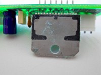
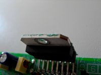
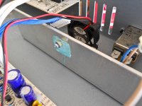
Ok. Here are a couple of shots that show the green stuff that is on the chip. Like I said, its hardened, and when I pulled the little board off of the big aluminum bar (which I assumed was acting as a heat sink), it acted like adhesive.
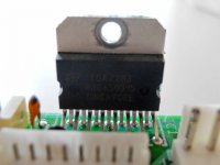
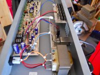
Also, you can see how the chip looks undamaged. I included a shot of the aluminum mounting plate and the entire inside to show the positioning of the plate.
I don't see the point in mounting it on a giant piece of aluminum if it isn't to dissipate heat, and yet, without a physical connection, it seems the heat sinking would be inadequate.
Anyone recognize this green stuff or know how to get it?
If I use something to keep the electrical connection from being made, I think I will ensure overheating in the future.
Attachments
It seems to be working fine, and the chip says it is a 100w power amp chip, which in this application is only producing 50, so I'm thinking that if the stock fan is clean and working, it should be ok. But, can anyone recommend a part number for an upgrade or an additional fan to put in along with this one?
Is the fan for the higher output avt models larger?
Is the fan for the higher output avt models larger?
Since the fuses blew this stopped any more damage such as the chip exploding.
That is a **** poor mounting job from the factory.
A proper insulating pad would have much less thermal resistance that that thick glob of goo that they used.
If you wanted to get real technical you could lap the chip on a piece of glass with some #600 grit emery paper as I have done here,
http://www.diyaudio.com/forums/plan...tor-insulation-mylar-coating.html#post2791028
And/or even add a copper heat spreader and use a thin peice of mylar between the heatspeader and the aluminium plate with a very thin layer of heatsink compound on both sides of the plastic film.
Potroast cooking bags are made of mylar and a layer or two would suffice as all it has to electrically insulate the chip from the aluminium heatsink plate.
You could also mount a small finned heatsink on the opposite side were the fan is blowing towards it, that would help tremendously as well.
Any 12v fan that will fit and can move more air would be good.
Providing that it is being supplied by 12v or so.
It is just a chipamp and there is nothing special about it take a look at the chipamp threads for some more great info on it.
jer
It must be insulated from the heatsink as the tab is at -Ve.
For reference scroll down to construction here,
Project 127
Hope this helps.
jer
For reference scroll down to construction here,
Project 127
Hope this helps.
jer
Ok. It looks like instead of a bridge of diodes, this has a rectifier chip KBU1003G. Anyone know how to test this thing on the board? I'm looking up the specs on it now.
It's not a 'chip' it's just four diodes in a plastic casing - just check it as a bridge rectifier (which is what it is).
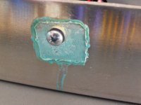
As for the chip, an insulating washer and heatsink compound is required - possibly the green paste used previously did both?.
I believe I see the outline of a mica wafer in the green goo in the photo, still stuck on the heat sink. I am not aware of any goo-only insulators. I agree it is crucial the metal tab on the IC be insulated from the grounded heatsink. Inspect that heat sink closely and see if there is or is not a thin mica wafer still there. The plastic shoulder washer is still on the screw.
- Status
- This old topic is closed. If you want to reopen this topic, contact a moderator using the "Report Post" button.
- Home
- Live Sound
- Instruments and Amps
- AVT50 Repair