Is anyone familiar with the Weber bias calculator?
Weber Bias Calculator
I am using it to calculate the dissipation watts and get results far from what I measure.
I have 2 6L6GC tubes sharing a 250 ohm (measured) resistor with 35 volts on the cathode and 450 volts on the plates. I also have a 68uF-100v bypass capacitor with it.
I measured the current from B+ to pin 3 and get about 30mA. But the calculator states I should be getting 67mA in each tube resulting in 30 watts dissipation. I trust my meter and measurements but don't know why the calculator would be so far off.
I also calculate the dissipation as: 450-35=415 and multiply by 0.030 to get 12.45 watts dissipation. Is that correct?
Thanks,
Daniel
pictures
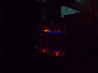
Here are some pictures,
First one is in cathode bias mode as I spoke about above.
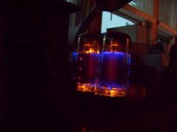
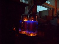
The others are in fixed bias mode with 45mA and 430v on the plates. Do these colors seem off? The plates are a little red but I'm not sure that's okay or not.
They are Electro Harmonix 6L6EH and seem okay given the tube data sheet for these: http://www.dougstubes.com/6l6-electro-harmonix.pdf
Here are some pictures,
First one is in cathode bias mode as I spoke about above.
The others are in fixed bias mode with 45mA and 430v on the plates. Do these colors seem off? The plates are a little red but I'm not sure that's okay or not.
They are Electro Harmonix 6L6EH and seem okay given the tube data sheet for these: http://www.dougstubes.com/6l6-electro-harmonix.pdf
Attachments
You have a 250 ohm cathode resistor with 35v across it. Ohm's Law tells me you then have 140ma flowing through it. That is 70ma per tube.
SO I do not find it surprising your plates are getting red.
That calculator is just a small program that makes that same calculation.
How did you make that 30ma reading? Did you pull the wire off pin 3 of the socket to insert the ammeter? Or did you install a 1 ohm resistor and take a voltage reading across it? Or what? And was the other power tube installed at the time?
Thanks, but the plates are not red in cathode bias mode. The way I measured it was the red probe on B+ and the black probe on pin #3. The tubes were in when I measured.
The redness is in fixed bias mode. According to the calculator 45mA is fine, but they are glowing a little red. There is about -30volts on the grid and the redness goes away at -36v, but I did not check the current at that point.
How did you come up with that figure of 140mA? V=IR
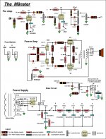
BTW: the pictures show more red on the plates than I see. The red is on the 'fins' of the plates and a little bit in the 'corners' where the are bent. The tubes are brand new from ebay. I'll post a schematic in a bit, I need to make some changes.
The redness is in fixed bias mode. According to the calculator 45mA is fine, but they are glowing a little red. There is about -30volts on the grid and the redness goes away at -36v, but I did not check the current at that point.
How did you come up with that figure of 140mA? V=IR
BTW: the pictures show more red on the plates than I see. The red is on the 'fins' of the plates and a little bit in the 'corners' where the are bent. The tubes are brand new from ebay. I'll post a schematic in a bit, I need to make some changes.
Last edited:
V=IR, so I=V/R. 250 ohms and 35 volts. 140ma or 0.14 amps. The current through the resistor has to come from somewhere, and the tubes are the only path, so I'd assume half of that per tube.
One source of error is screen current. The cathode carries not only the plate current but also the screen current. SO we generally subtract a few milliamps for the screen. But it doesn;t seem real likely your screens are conducting 37ma of the 67ma.
Yes, I assumed the tubes were in place, otherwise they couldn;t cunduct any current at all.
Sorry about that... It was a real 'duh' moment. And yes both tubes were in, I misread. Would I take a measurement of screen current from the screen, pin 4 to B+ or to the filter cap? The screen voltage is only 1v less than the plate.
One thing I thought of: That 250 ohms is shared, so in parallel, shouldn't that be 500 ohms per tube? Since the voltage in parallel does not change, and the resistance does, it calculates correctly. 35/500=0.07
And what about the bypass cap on the cathode, would that be a factor?
One thing I thought of: That 250 ohms is shared, so in parallel, shouldn't that be 500 ohms per tube? Since the voltage in parallel does not change, and the resistance does, it calculates correctly. 35/500=0.07
And what about the bypass cap on the cathode, would that be a factor?
You have 820 ohm screen resistors. Measure voltage drop across them and calculate with Ohm's Law.
The resistor is shared, so the current through it is for both tubes. You can imagine it was one resistor per each, but isn't it just as easy to divide the direct calculation by two? I mean it doesn't really matter how you get that factor of 2 into the calculation, as long as it reflects half the current flows through each of the tubes.
The resistor is shared, so the current through it is for both tubes. You can imagine it was one resistor per each, but isn't it just as easy to divide the direct calculation by two? I mean it doesn't really matter how you get that factor of 2 into the calculation, as long as it reflects half the current flows through each of the tubes.
Thanks Enzo,
I changed the screen resistors to 470 ohms. I used 820's because the voltage on the screens were at or slightly above the plate voltage. In fixed bias mode, it is not, there is one-two volts less on the screens than the plates. But in cathode bias mode, one tube is one volt less and the other is one volt more. The cathode voltage 35v and the current is 27.2mA and 30.4mA respectively. There is a 3 volt and 2 volt drop across the screen resistors, also respectively. That calculates as: 19.1mA and 8.5mA, giving me 46.3mA on one tube and 38.9mA on the other, with a total of 85.2mA total.
I did pull one tube, the 27.2mA one and got about 48mA of current and 30 volts on the cathode. Plate voltage was 446 and the screen was 448, with the same 2 volt drop across the resistor.
FYI: this amp was a Hammond AO 68 that I gutted and put the schematic above into it. I am wondering if the power transformer for the original could have anything to do with what I did. The original setup was with 7591 tubes, but I'm using 6L6's.
It really sounds great! And the plates are not red. It is quieter now since I changed the screen resistors. I am just wondering about the math and the measurements because my goal is to sell it.
Daniel
- Status
- This old topic is closed. If you want to reopen this topic, contact a moderator using the "Report Post" button.
- Home
- Live Sound
- Instruments and Amps
- Weber bias calculator