Hello everyone,
I'm new to this board. The main reason is because I encountered a noise problem with my DIY JCM 800 2204.
It plays well on low master levels. If I turn up the gain or play the strings very hard, I get a buzzing sound out of it. However, the main volume does not cause a noise.
Now I'm wondering, where the problem may lie. I'm sure you experts can help me out. Is it wiring, the tubes or caps? I don't know.
I've attached a sound file where you can hear the noise. I'm turning the master knob up and down.
Once the amp runs smoothly I'm willing to share my documented building process.
With regards,
Cypher
Attachments
Should be in Instruments and Amps forum? I'm sure a Mod will oblige.
I've moved it.
Maybe share a bit of your progress now, at least the schematic for those not familiar with the JCM.
Is it like one of these layouts?
Have you compromised or omitted any parts?
Is it point to point or PCB, if PCB did you do the layout?
Is it like one of these layouts?
Have you compromised or omitted any parts?
Is it point to point or PCB, if PCB did you do the layout?
Attachments
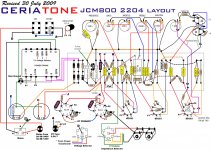
I used the layout you posted - Ceriatone. I exactly rebuild the amp, using only the best parts on a turret board. Only difference for me: no resistors on big cap & standby. And no voltage selector & impedance selector, but instead hardwiring to 230v and 8ohm. 4ohm line is connected to board directly.
I realised my poor heater wiring and completly redid it the proper way - twisting, angles, etc. The amp sounds different, but anything from normal. I still get a high pitched noise when strumming hard or turning off. Even if gain goes up more now, its a similiar effect then before. If I turn up volume and gain as much as it is possible without getting buzz, the guitar still plays pretty silent. It's supposed to blow me away on that level.
Biasing tubes is not really possible, as I don't have any voltage on the 1ohm resistors on standby. Turning standby off sometimes gives me a voltage and sometimes its zero. Weird.
I'm really frustrated and I'm beginning to think that I should have invested the 300 bucks in a real amp... Well, but now as someone answered, I dont wanna lose hope.


Update: I rewired input/output by placing input closer to the volume pot and preamp tube 1. Also output wires run accross the side to the power side of the amp, where there is the jacks and on the way the power tubes.
Result: 1. on low gain, hi input - lots of volume that blows you away. No hum, but tube distortion when chording sounds bad.
2. High gain, hi input - same result as in the beginning. Pig squeel which wont go away easily, even after turning gain down. Distortion sounds awful.
3. Low gain, low input - when strumming hard i get the same results as in the beginning. A harsh, hi hat kinda hiss is included on every loud note.
4. Low gain, low input - same as 2. But worse.
When going to standby or turning the amp off, it goes silent much more pleasingly. No more blobb or mega loud hiss ( just a little hiss).
I'm on my way. If anyone has suggestions besides chopsticks, I'd appreciate that.
And why would we not be serious? You started there, obviously it is the first step.You serious? The first thing i did was moving the wires around.
You need to post some clearer pictures. Turn on more lights or usse a flash.
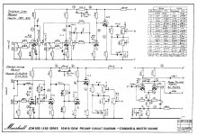
In the second picture it looks like the input jacks are right across from the output tubes. Is this correct? That doesn't match the layout. The schematic above is wrong, it's for the 1987 and 1959 models. The 2204 has just two input jacks like the layout and the two triodes of the first tube are cascaded. Where are the 5.6K resistors located? Are they on the output tube sockets like the layout?
Where is your bias set? The standby switch has to be in the "Play Mode" to measure any voltage across the 1 ohm resistors.
@printer2: yes you are right. Thats the first step. Thanks.
@loudthud: sorry for the pics. I finished work at 12 pm and didnt have a light. Ill post new ones tomorrow. I have rewired the amp so that input jacks match schematics. 5,6k resistors are the wooden looking ones- they are 5 watts each and are soldered to the output tubes. Cascaded tubes means they are linked to the board together right?! Should be the case.
And about bias: its at 35 mv at screen grids on standby on.
There are a lot of wires that are not twisted with another wire. Any "enclosed loop area" of a pair that's not twisted together will act as an antenna for every time-varying electromagnetic field.
There should at least be an "input signal" and "input signal ground" wire pair, and that pair should be twisted tightly together, ALL the way from the jack to wherever they connect (maybe across a resistor to ground, at a grid input?). Ditto for the output pair. Ditto for all DC power/gnd pairs. Ditto for the AC input pair and for the rectified AC pair.
The layout mostly doesn't lend itself too well (for me at least) to figuring out what pairs go together, and the wiring scheme looks like it just mixes a lot of the grounds together, which might mean that (unless you break up the ground buss and implement real star grounding) a lot of the low-voltage wiring might be better if it closely followed the ground buss, to minimize the enclosed loop areas.
Anyway, for now I'd try sorting out the input signal/ground pair and make sure they don't encompass any area between them. And I'd also look at the ground reference voltages' connections to the star ground. For example, where the input pair connects across a resistor between a grid input and gnd, there should be a connection to the ground end of that resistor, that goes to, um, ground. Anyway, if that connection SHARES lengths of conductor with other ground-returns, before it gets to the star ground, that could be a problem. I'd try running a dedicated wire from there all the way to the star ground point (and disconnecting the original connection that went from that point to the rest of the grounding system). Actually, I'd do the same thing for every small-signal input ground reference voltage, for all tube inputs where it's applicable.
Last edited:
5,6k resistors are the wooden looking ones- they are 5 watts each and are soldered to the output tubes.
Those resistors should be 1/4W or 1/2W carbon or metal film. Wirewound resistors might not stop oscillations as intended. Many simple DVMs will detect oscillations. Simply set the meter to AC volts and connect the leads across the speaker terminals. With no signal going through the amp the reading should be very low, perhaps 0.025VAC. Turn up the volume, master, treble and presence controls. If the reading jumps up to 5 or 10VAC, you have an ultrasonic oscillation.
Cascaded tubes means they are linked to the board together right?! Should be the case.
The original Marshall amps like the JTM45 and the ones Hendrix used were copies of the Fender Bassman 5F6A. These had two input channels and two Volume controls with 4 input jacks. The amps like the 2204 re-arrange the components to provide a single channel with more gain and a Master Volume control. With more gain, there is a greater tendency for noise and parasitic oscillation. Layout is more critical.
And about bias: its at 35 mv at screen grids on standby on.
This does not make any sense, but could just be a technical translation problem. Your profile does not say what country you are from, but with 230V mains, it can't be the USA. 35mV would be good if it is measured across the 1 ohm resistors between the cathode (pin 8) and ground. The "Screen" grid is connected to pin 4.
Yeah, or the oscillations could be in the Megahertz.
One reason to clean up the wiring is that, in its current state, it enables the potential for two types of hidden feedback paths, which could cause oscillation-type phenomena: 1.) The output pair (or maybe even the DC PSU wiring, or ground returnss) could act as a transmitting antenna and sensitive or high-impedance input sections could act as receiving antennas. 2.) Ground-return currents using shared conductors could enable one area's ground-return currents to induce voltages that sum with another area's input signal.
Either or both of those have the potential to induce uncontrolled oscillation, or damped oscillation, and/or ringing, depending on the levels and gains at the moment, etc.
Also, are there decoupling or bypass capacitors in that design, wherever an active device might make sudden demands for changes in current from the power supply rail? The decoupling caps act as a small point-of-load power supply, to provide for transient current demands, which, if forced to come through the inductance of the rail, would cause voltage spikes on the rail. Could that actually become a form of positive feedback and cause high-frequency oscillation. It does in solid-state circuits, which is why there is usually also a small-sized bypass cap used across each device's power/gnd pins.
Wow! Thats some extremely valuable information! Im working on understanding what you said and change that in my layout.
Things I already did:
1. Measure AC voltage across speaker terminals - without any input plugged in:
a) ~0 at standby
b) 43.2V (!!) with amp running, master&volume max
Even if there is very little hum without input, I get a huge oscillation reading.
I wasn't able to measure with input plugged in on that levels, because Id get a scream out of the amp so loud my neighbours thought someone died. Guess the AC would be significantly higher.
2. Remeasure Pin 8 across 1 ohm resistor on output tubes: ~ 38mV. Thats cool.
What Im going to do after reading your replies:
1. Seperate grounding for input jacks, going to star ground directly.
Question: i have shielded input wires, so no need to twist anything right?
2. Replace 5,6k/5watt wirewound resistors (1.50 euros) with metallfilm 1/2 watt (20cents) - local store was out of metallfilm 5.6k at that time. Thought its not a big deal, right...
3. Output/input seperation, because of the antenna thingy.
4. Seperate grounding for every low voltage signal.
@gootee: so caps could also be a cause for HF oscillation. What can you do about it? I dont know if there are any decoupling caps. I didnt add anything myself to the original layout.
Last edited:
Man... I cannot edit my post, so I have to post a new reply.
Measuring speaker voltage without input was pointless I think. I remeasured with guitar plugged in. On every hiss I saw a voltage peak, going up to 1,5V and more (it shows about 0,7V max while playing pleasant notes). With more hiss I got a bigger AC voltage. So that's a clear indication that some bad oscillation is going downtown.
Connecting ground from input jack directly to star grounding had a positive effect!
a) On low input I can crank up the master level to max now, without getting a pig squeel. However, annoying tinny souding, rattling hiss/buzz is still present while strumming a bit harder or playing on higher volumes.
b) On high input I get the pig squeel only when master is at about 90%. So thats an increase there, from 40% to 90%! Awesome. However, strumming notes on high sounds terrible, obviously because buzz is amplified more than on low.
I recorded the hiss/buzz noise I was talking about. Unfortunately, you cannot hear the full amount of pain this buzz causes on the recording, mainly because my phone doesn't catch the highest frequencies. But you'll get the idea.
Please have a look.
Attachments
Check to make sure you have B+ to all your bulbs. (It happens)
Then tap each one with the eraser of your pencil to find the microphonic one.
Your correct with your shielded input wire. (No twist)
Generally speaking, you ground this input lead directly at the first tube socket. If it works at the star point, OK I guess.
Make sure the 68K gridstopper on the first tube is short and connected directly to the socket.
I can't gain much from your pictures from all the black wires, sorry.
Tom's advice is more in depth, these are just some other things to check/tips.
Don't know if you have a good set of test clips but it would be interesting to have you clip a volt meter across the cathode resistor of each tube in turn and play something at a lower level without the effect and then loud enough for it to happen. Theoretically the voltage should not change much if things are working right. I am wondering if we have some grid blocking going on also?
- Status
- This old topic is closed. If you want to reopen this topic, contact a moderator using the "Report Post" button.
- Home
- Live Sound
- Instruments and Amps
- DIY Project - preamp-gain causes noise