I am putting together a guitar amp, and hoping for about 40 watts RMS.
I chose 6L6GC as the robust tube of choice (I hate EL34s, especially newer unreliable crap), and am aware of bad tube-eating designs of the past.
I am limited by what I have on hand:
(1) a good Ultralinear 100w Output tranny (5K Zprimary). This will allow me to expand power later if I can beef up the powersupply (see below).
(2) a nice 300-0-300 HV power tranny, with a 5 and 6.3v winding. This is underpowered, but I hope to squeeze more out of it by leaving the 5v winding unused, and not overloading the 6.3v winding. I tested these windings with loads, and found:
600v c.t. @ 160 mA (from a load test)
5v rect. heater @ 2A
6.3v main heater @ 4A (before sag)
This doesn't match any current Hammond, but looks like a mix. Its a no-name brand from the 60s or 70s (surplus), possibly JAN.
When I use solid-state diodes, I can wire it full-wave with a 10H choke and a stacked cap giving 100uF (4x 100uF series/parallel 450v), and it looks like I can count on 520 volts under a real load (projecting 4x 6L6 at 40 mA each, push/pull).
(3) 520-540 volts is just a little too much to put on the tubes (even good 6L6GCs), so I'm also opting for self-biasing, so I can drop about 40-50 volts across the cathode resistors). This leaves me at the edge of the design-center max for the 6L6GC, but the low idle current (40mA/tube) will help prevent too much dissipation.
(4) I intend actually to use 6BG6s, which can take 700 volts anyway (topcap plates) without worries. But in a pinch I should be able to put in a set of 2 or 4 6L6GCs made to take 500 volts. I'm going to rig something special to protect the plate caps and people's fingers, and to hold the tubes in regardless of orientation. Also I will probably float the mounting so that the tubes have some shock-insulation, to improve microphonics and protect the tubes from banging.
(5) Ultralinear Topology: I intend to take advantage also of the Ultralinear tappings, so that I can avoid building two extra powersupplies (screen and bias). This should allow lower idle current without undue distortion.
(6) Four Output Tubes: The idea here is to lighten the current load on each tube, and also drop the internal output impedance of the power stage.
(7) The splitter/ driver circuit is still up in the air. I haven't chosen a topology for this, and wish to hear what others think from their personal experience (comparisons) especially in regard to keeping the output stage balanced as tubes age, with low maintenance, and a good match to provide current to drive the output stage grids, in case they draw current.
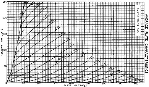
(8) Looking at the basic loadline, I find there is a small 'danger' zone at the lower-right, where the voltage across the 6L6s could climb above 500 volts (the design max) as the tube shuts off, if the input signal were driven hard enough to push the stage into class B temporarily... I think I can get a good 40 watts without too high an input voltage, but in any case the 6BG6s will be able to take the overdrive/classB. Its only the 6L6CG scenario that worries me. Any comments would be appreciated. But with self-bias, there is much more headroom, even with the 6L6s.
(9) The 'guitar-amp' sound will be mostly derived from manipulating the input section, so I would really like to hear what people have to say about good preamp designs re: guitar sustain and harmonic content.
(10) I'd like to have a simple but effective Parametric EQ, something like the EQ in a BOSS MT-2 pedal (bass, mid/Q, treble) only modded for a better choice of frequency ranges. I could use a hand on that, again, I want to use tubes for this (maybe an 12AT7 or two).
Obviously I can do this in stages, as I get the results I need at each step, and move on to the next addition/mod.
Right now, I have on the table the following issues,
and could use some advice:
(a) Grid Stoppers: (1.5k - 5.6k ohm range?) I'd like advice on these, I'm not worried about losing a bit of signal, but would rather have stability and immunity from RF...
(b) Screen Limiters: (450 - 680 ojm range?) I read a discussion somewhere on here about guitar amps, and the problems with EL34s etc., along with typical values and preferred. But any input or advice would be good, especially as apparently screen current will significantly affect sound as well as tube-life.
(c) Grid-Leak / Input: (100k - 470k? ) with self-bias, I should be able to tolerate values a little higher, but I am more inclined to want the self-bias on the grids to work well, rather than 'maximize' input Z here. Any advice?
(d) Cathode Bias: (500 - 1.5k ohm ?) I found experimentally that to get a good 48-50 volts on the grids and keep the current down to near 40 mA per tube, I needed at least 1.3k cathodes (with Svetlana 6L6GCs).
But the issue doesn't stop there, because I could use one large common cathode resistor per tube-pair (e.g., 650 ohm). However, Hafler found that a 10 ohm common resistor was apparently the right amount of 'common resistor' to minimize intermodulation distortion (presumably the rest of each cathode resistance was separate). Any leads on this would be welcome.
Also whether or not to bypass, as it seems I would trade off lower output impedance (which may be unnecessary with 4 tubes) against the sound degradation that say 47uF electrolytics would introduce....please tell me what you think!
Other issues I need to settle are:
(e) Input isolating caps for input each side (.22uF? 600 v?) of power stage. Since its not a hi-fi, perhaps polystyrene or something not too expensive could go here?
(f) RF inhibitors and stabilizer additions:
Here I'm thinking of an RC series between screen and plate on each side, an RC series across the primary of the output xformer, and also a 100 ohm resistor across the Secondary in case a speaker is unplugged or goes open-circuit.
Any other safety features would be also welcome.
I am going to place an internal fuse between the HV B+ and the output xformer primary c.t., but what else can I do to protect tubes and xformer from spikes due to failure or user-error?
Thanks for any input or links you could offer.
Nazaroo
I chose 6L6GC as the robust tube of choice (I hate EL34s, especially newer unreliable crap), and am aware of bad tube-eating designs of the past.
I am limited by what I have on hand:
(1) a good Ultralinear 100w Output tranny (5K Zprimary). This will allow me to expand power later if I can beef up the powersupply (see below).
(2) a nice 300-0-300 HV power tranny, with a 5 and 6.3v winding. This is underpowered, but I hope to squeeze more out of it by leaving the 5v winding unused, and not overloading the 6.3v winding. I tested these windings with loads, and found:
600v c.t. @ 160 mA (from a load test)
5v rect. heater @ 2A
6.3v main heater @ 4A (before sag)
This doesn't match any current Hammond, but looks like a mix. Its a no-name brand from the 60s or 70s (surplus), possibly JAN.
When I use solid-state diodes, I can wire it full-wave with a 10H choke and a stacked cap giving 100uF (4x 100uF series/parallel 450v), and it looks like I can count on 520 volts under a real load (projecting 4x 6L6 at 40 mA each, push/pull).
(3) 520-540 volts is just a little too much to put on the tubes (even good 6L6GCs), so I'm also opting for self-biasing, so I can drop about 40-50 volts across the cathode resistors). This leaves me at the edge of the design-center max for the 6L6GC, but the low idle current (40mA/tube) will help prevent too much dissipation.
(4) I intend actually to use 6BG6s, which can take 700 volts anyway (topcap plates) without worries. But in a pinch I should be able to put in a set of 2 or 4 6L6GCs made to take 500 volts. I'm going to rig something special to protect the plate caps and people's fingers, and to hold the tubes in regardless of orientation. Also I will probably float the mounting so that the tubes have some shock-insulation, to improve microphonics and protect the tubes from banging.
(5) Ultralinear Topology: I intend to take advantage also of the Ultralinear tappings, so that I can avoid building two extra powersupplies (screen and bias). This should allow lower idle current without undue distortion.
(6) Four Output Tubes: The idea here is to lighten the current load on each tube, and also drop the internal output impedance of the power stage.
(7) The splitter/ driver circuit is still up in the air. I haven't chosen a topology for this, and wish to hear what others think from their personal experience (comparisons) especially in regard to keeping the output stage balanced as tubes age, with low maintenance, and a good match to provide current to drive the output stage grids, in case they draw current.
(8) Looking at the basic loadline, I find there is a small 'danger' zone at the lower-right, where the voltage across the 6L6s could climb above 500 volts (the design max) as the tube shuts off, if the input signal were driven hard enough to push the stage into class B temporarily... I think I can get a good 40 watts without too high an input voltage, but in any case the 6BG6s will be able to take the overdrive/classB. Its only the 6L6CG scenario that worries me. Any comments would be appreciated. But with self-bias, there is much more headroom, even with the 6L6s.
(9) The 'guitar-amp' sound will be mostly derived from manipulating the input section, so I would really like to hear what people have to say about good preamp designs re: guitar sustain and harmonic content.
(10) I'd like to have a simple but effective Parametric EQ, something like the EQ in a BOSS MT-2 pedal (bass, mid/Q, treble) only modded for a better choice of frequency ranges. I could use a hand on that, again, I want to use tubes for this (maybe an 12AT7 or two).
Obviously I can do this in stages, as I get the results I need at each step, and move on to the next addition/mod.
Right now, I have on the table the following issues,
and could use some advice:
(a) Grid Stoppers: (1.5k - 5.6k ohm range?) I'd like advice on these, I'm not worried about losing a bit of signal, but would rather have stability and immunity from RF...
(b) Screen Limiters: (450 - 680 ojm range?) I read a discussion somewhere on here about guitar amps, and the problems with EL34s etc., along with typical values and preferred. But any input or advice would be good, especially as apparently screen current will significantly affect sound as well as tube-life.
(c) Grid-Leak / Input: (100k - 470k? ) with self-bias, I should be able to tolerate values a little higher, but I am more inclined to want the self-bias on the grids to work well, rather than 'maximize' input Z here. Any advice?
(d) Cathode Bias: (500 - 1.5k ohm ?) I found experimentally that to get a good 48-50 volts on the grids and keep the current down to near 40 mA per tube, I needed at least 1.3k cathodes (with Svetlana 6L6GCs).
But the issue doesn't stop there, because I could use one large common cathode resistor per tube-pair (e.g., 650 ohm). However, Hafler found that a 10 ohm common resistor was apparently the right amount of 'common resistor' to minimize intermodulation distortion (presumably the rest of each cathode resistance was separate). Any leads on this would be welcome.
Also whether or not to bypass, as it seems I would trade off lower output impedance (which may be unnecessary with 4 tubes) against the sound degradation that say 47uF electrolytics would introduce....please tell me what you think!
Other issues I need to settle are:
(e) Input isolating caps for input each side (.22uF? 600 v?) of power stage. Since its not a hi-fi, perhaps polystyrene or something not too expensive could go here?
(f) RF inhibitors and stabilizer additions:
Here I'm thinking of an RC series between screen and plate on each side, an RC series across the primary of the output xformer, and also a 100 ohm resistor across the Secondary in case a speaker is unplugged or goes open-circuit.
Any other safety features would be also welcome.
I am going to place an internal fuse between the HV B+ and the output xformer primary c.t., but what else can I do to protect tubes and xformer from spikes due to failure or user-error?
Thanks for any input or links you could offer.
Nazaroo
(a) Grid Stoppers: (1.5k - 5.6k ohm range?) I'd like advice on these, I'm not worried about losing a bit of signal, but would rather have stability and immunity from RF...
Reading over the thread on tube tracer building, I was impressed by the fact that even in what seems like simple stable circuits, tubes were still prone to oscillation and excitation, so much so that relatively frequently the tube tester lads were adding resistors to prevent it.
This seems to underline the idea that Grid Stoppers are not merely 'just in case' options, but necessary circuit elements.
Especially when later users are likely to experiment with substituted tubes, a choice of grid stopper that allows the amp to behave under a variety of conditions seems like a good design goal.
In my mind, one can't solve every possible event, but if I limit the list of possible output tubes down to a reasonable subset for this topology and voltage range, I get this:
(1) 6BG6 (first choice).
(2) 6L6GC (2nd choice).
(3) EL34 (not a preference, but a likely experiment to beware of)
(4) 5881 (this is where it gets iffy, because of lower voltage ratings).
I think I may place a sticker inside warning future users not to try lower voltage "6L6"s or 6V6s. But the EL34 should actually work, PROVIDING I prevent too much screen current from flowing. So here is a case where even though I don't like EL34s, it would be smart to design with their possible use in mind.
In the case of the 5881s, switching in some kind of B+ voltage drop option might be workable (a "5881" switch of some kind).
I think I might need some help on that idea, but it can wait.
Now, the grid stopper choice doesn't seem to be too critical, although one thing comes to mind:
Even a low value grid stopper might start eating up driver-voltage if there is grid current happening when the amp is pushed. So it looks like the choice should be as low a value as possible, given the range of tubes contemplated.
What IS critical here then, is to choose a value that doesn't choke off driver voltage to the grids, while still effectively preventing RF/oscillation and instability.
The first thing I am looking at is what other people have done.
MARSHALL: I don't think early Marshalls were well-designed, and even though they may have some 'vintage' sound, I don't think their choice of grid-stoppers will be particularly credible.
Nonetheless, the JCM800s, which use EL34s (6CA7), all have 1.5k grid stoppers.
FENDER: Here I think there might be something to note. I see in the Fender Twin 100w that for 5881s they apparently shared 1.5k grid stoppers (one for two tubes on each side = 750 ohms/tube? ). Still that is not the tube of choice.
TRAYNOR: This Canadian amp co. presents some unusually conservative and reliable designs, so its worth looking at.
On the 1966 YVM1 Voicemaster they added 10K grid stoppers for 7027 tubes (although many people seem to have substituted EL34s in these old Traynors). This seems unusually high...
The YBA1A Bass-Master Mk2 (1971) has added 1.5k grid stoppers, probably following FENDER designs, and accommodating USA-made 6CA7s (high power EL34s).
Still, some designs leave out grid-stoppers entirely, right up to 1970 revisions, such as the YBA-3 Custom (4x 6CA7s).
HIWATT: Seem to have put original thought/experiment into grid stoppers; they have 22k grid stoppers in their 4xEL34 output stage (200w).
MESABOOGIE: they use 220 ohm grid stoppers on their Musicman GP-3, with (EL34?)6CA7s, but they are also using opamp drivers....
Their 1972 OrangeAmp MkII however uses 2.4k grid-stoppers on 4xEL34s.
The VOX AC-100 again deviates, with 47k grid-stoppers on only two of the 4 EL34s (not shared!).
Looks like some plagarism in design, perhaps following tube-maker guidelines rather blindly, accompanied by a few maverick experiments, but little consistency or clarity in design constraints...
Anybody have any experience in this aspect of design?
The high values may not be good design choices, (stability problems may be better solved with different methods) , and other variants may be to save on parts, rather than provide 'best design' examples.
If part of the goal was to limit grid current in class AB/B modes, there might be more effective ways of doing that without sacrificing driver voltage.
I don't think its overly critical. Use the minimum value needed to attenuate RF.
1.5K to 5.6K.
It forms a low pass filter with the miller capacitance of your particular tube.
Generally fairly large values can be used without loss of "tone" or audio frequencies, as it filters much higher radio frequencies.
Once you get up to around 50K - 100K, then treble loss may be noticeable. Values this high may have been used to "voice" the amp rather then actually needing to be this high to tame oscillations.
Higher values can also reduce blocking distortion in high-gain stages and can/will start to roll off treble. ex:470K
I don't think its overly critical. Use the minimum value needed to attenuate RF.
1.5K to 5.6K.
It forms a low pass filter with the miller capacitance of your particular tube.
Generally fairly large values can be used without loss of "tone" or audio frequencies, as it filters much higher radio frequencies.
Once you get up to around 50K - 100K, then treble loss may be noticeable. Values this high may have been used to "voice" the amp rather then actually needing to be this high to tame oscillations.
Higher values can also reduce blocking distortion in high-gain stages and can/will start to roll off treble. ex:470K
I'm unfamiliar with "blocking distortion":
Can you explain that a little bit, or point me somewhere I can learn about it?
Its nice to know that some of the higher values found might be attempts at 'voicing' experimentally. In that case I'd probably want to avoid that until I am ready for 'fine tuning' of guitar-amp sound and behavior. Right now, I'm concentrating on good design practice, stability and tube-life.
If the values are in part selected by Miller capacitance, then there should be either a reliable calculating method and/or a simple chart recommending values for each tube type.
Where can I find that kind of accurate info?
P.S. the values you suggest still seem very high: and cut significantly into driver voltage, it looks like.
Also, I'm a little unhappy with an "any value between x and y will do" method of design.
If we know the tubes, and follow good construction practice,
we should be able to nail down the best compromise value,
based on performance under each set of tubes.
This of all design parameters should be a science, and constrained by a solid theoretical foundation.
"There can be only one!" value that meets the criteria.
oops pressed quote instead of edit...(a) Grid Stoppers: (1.5k - 5.6k ohm range?) I'd like advice on these, I'm not worried about losing a bit of signal, but would rather have stability and immunity from RF...
MARSHALL: I don't think early Marshalls were well-designed, and even though they may have some 'vintage' sound, I don't think their choice of grid-stoppers will be particularly credible.
Nonetheless, the JCM800s, which use EL34s (6CA7), all have 1.5k grid stoppers. The schematic also allows 6550s here!
Anyway, I wanted to noted that the JCM800 also allows 6550s as the powertube.
Last edited:
OK, then pick your tube, calculate the resistor based on your specific tubes miller effect.
General questions get general answers.
Weather or not the RF cutoff is at 15Khz or 20Khz is a matter of semantics, both filter out the RF and let the highest guitar frequencies through, hence the range of resistors.
Sometimes its nice to have elbow room, a "range" might allow for different tubes types while still doing the job.
The effect on audio attenuation is very minimal.
Grid Stopper Resistor Calculator
Blocking Distortion
Last edited:
Yes, its easy. All you need is an accurate UHF/microwave model of the valve in its holder, with all the surrounding circuitry (including all parasitic elements) and wiring (regarded as a set of loaded UHF resonators). Put all this into a good EM wave simulator, and vary the valve parameters to represent different samples and the effects of ageing or variations in mains supply voltage.nazaroo said:Also, I'm a little unhappy with an "any value between x and y will do" method of design.
If we know the tubes, and follow good construction practice,
we should be able to nail down the best compromise value,
based on performance under each set of tubes.
This of all design parameters should be a science, and constrained by a solid theoretical foundation.
"There can be only one!" value that meets the criteria.
Alternatively just use 1-10k grid stoppers like everyone else, including those who understand RF. If you have a really poor layout, like some guitar amps, then you might need to go up to 100k. If you like 'tube rolling' then use 100k+ and adjust your treble level by swapping valves with different amounts of Miller capacitance. Sensible people would use a tone control, which I think is what you are proposing.
thanks for the great input here.
You are surely right to point out that a rolloff difference of 20kHz vs. 25kHz would probably be inaudible, and might give headroom for tubes with varying Miller capacitance.
I like that idea, and if I understand correctly, you would choose the value that rolls off above 20kHz for the worst tube, and hope that no oscillations occur between 20kHz and whatever the rolloff would be for the better tubes (lower Miller cap?).
As for the second post, I think you are right in pointing out that one can go too far in trying to do it 'right'. There is no point in having to build a half-million dollar test bench to nail down a 20 cent resistor.
But yes, I'd prefer to do audio frequency response adjustments using a good tone-control, rather than limit the fundamental design.
P.S.
My big concern here with grid stoppers is limiting the driver swing voltage.
The main idea with a guitar amp is power, and lots of it, and we don't want to waste driving voltage in a resistor
when it can pump the power tubes instead.
Its all about getting max power to the speakers (safely) for a given cost/set of tubes & xformers.
Even distortion is a secondary issue, if not actually desirable in a guitar amp.
In my mind, the only distortion I want to limit is intermodulation distortion, and powersupply noise contributions.
I actually would like to have a knob that turns up 2nd harmonic distortion to any arbitrary value!
Also, plainly, using a 100k grid stopper to 'correct' for a horribly bad amp layout has got to be the worst design approach possible.
Better to do all you can to design the best possible layout and shielding to minimize RF, interference, noise, and feedback problems, THEN see what value you need...
Last edited:
Just for contrast, it might be good to look at a few older solid designs:
The Western Electric Model 142A (6L6s) uses only a 100 ohm grid stopper! Such classic designers tended to deal with parasitic RF directly using other methods, rather than choke out driver voltages.
On the other hand, one RCA design (mi9377) sports 47k grid stoppers on a 4x 6L6-G design (lower voltages). This seems rather large, especially when we also see regulated screens and RC networks on both halves of the output xformer primary.
Looks like a lot of effort went into bullet-proofing this design, but maybe a better layout would have accomplished more!
The Natural Horizon 20 uses a mere 470 ohms per 6L6G tube in a 30 watt design.
Someone felt it necessary to place 5 ohm resistors on the cathodes of a dual 807 design (high power version of a 6L6).
We see a relatively high value (22k) in Bogen's DO-30A (KT66 pentode mode)
The model A-30 Circlotron gets by with 120 ohm grid stoppers, on its 6BG6Gs.
A 2005 design by Wes Kinsier doesn't use any at all, apparently with good results...
An Ultralinear design from the 1990s using 6CA7s uses only 100 ohms of grid-stopper (and a 10 ohm common cathode as per Hafler's recommendations).
DuKane's 1A475C (100w) with 4x 6CD6GAs uses 10k grid-stoppers only on the second pair.
The "Lil Tiger" mod by Forrest Cook stuffs in 1k grid stoppers on its 6BQ5s.
The Altec Lansing A-340A (2x 6550s) also skips them entirely, preferring instead to invest in a regulated screen supply and a multistage FB loop.
The Maestro (1951) has none on its 6145 outputs.
Gotham's PFB-150WA avoids grid stoppers in its 811A triode design.
No grid-stoppers are to be seen in Altec Lansing's 1570B, which sports a pair of 811As.
Yet another RCA (MI-12246) has none on its 811As.
The Altec Lansing 260A uses only 100 ohm grid stoppers on a pair of 813s, with a thousand watts and dangerously high voltages.
As a trend, older amps have lower value grid stoppers, or none at all.
Is this development an evolution to compensate for an RF polluted environment?
Last edited:
 This is clearly a musical instrument amplifier discussion, please read the headers on both Tubes / Valves and I & A forums as that makes it clear where this thread belongs. Thanks! It's moving..(Moved!)
Older valves tend to be bigger, and have poorer gain at UHF so there is less risk of parasitic oscillation. It could also be that older designers are more likely to understand RF as well as audio, so less likely to make their audio amplifier stages also look like a UHF oscillator.As a trend, older amps have lower value grid stoppers, or none at all.
Grid stoppers (on the first stage) can reduce RF coming in from the outside, but mostly they stop the stages from oscillating.
On a separate issue, ultimately IM and harmonics have the same origin in non-linearity.
Older valves tend to be bigger, and have poorer gain at UHF so there is less risk of parasitic oscillation.
So, is this directly related to older tubes having higher Miller capacitance?
Yes I'd tend to believe that the older engineers were more RF-savvy, although they couldn't have predicted the modern RF-polluted environment.It could also be that older designers are more likely to understand RF as well as audio, so less likely to make their audio amplifier stages also look like a UHF oscillator.
I still haven't got much input on modern RF issues vs. the 1960s when there wasn't so much transmission at every band.
This is interesting, the distinction you are drawing here.Grid stoppers (on the first stage) can reduce RF coming in from the outside, but mostly they stop the stages from oscillating.
Obviously oscillation can go all the way down to sub-audio (motor-boating).
What are the low-frequency issues and considerations here?
I am intrigued:On a separate issue, ultimately IM and harmonics have the same origin in non-linearity.
Since some designs have different ratios of IM vs. HD,
what are the controlling parameters here?
I am tending to believe at the moment that IM comes mainly from poor interaction between tubes and powersupply hum.
I might believe there is a small component of IM coming from mismatches or imbalances in a Push-Pull topology, (or rather IM falls into visibility and consideration when HD is cancelled out by Push-Pull arrangments!).
But do you think IM is directly related to operating a tube in a non-linear zone? How so?
No. Wider spacing means lower UHF gain because of transit time effects. Old valve bases and sockets can be made from materials which are lossy at RF. New valves are mainly of all-glass construction.nazaroo said:So, is this directly related to older tubes having higher Miller capacitance?
None. Grid stoppers prevent VHF/UHF parasitic oscillation. They have no effect on lower frequencies, unless too big in which case they will affect HF loop instability if there is global NFB.What are the low-frequency issues and considerations here?
If an output contains Fourier components not present in the input (including all inputs such as PSU) then they arise from nonlinearity - this is simple algebra and trigonometry. Valves are not the only source of nonlinearity, but they are a major source. Sometimes harmonics can be cancelled, sometimes IM can be caused by re-entrant effects, so levels are not necessarily equal but they do arise from exactly the same source.But do you think IM is directly related to operating a tube in a non-linear zone? How so?
Hum IM is merely one type of IM, and that comes mainly from valve nonlinearity as the PSU hum sweeps the bias point up and down the valve characteristic. All valves work in a "non-linear zone" - the only issue is how much nonlinearity is there?
If you haven't yet read it, try to get hold of a copy of the Radiotron Designers Handbook. That will cover lots of these issues. It is available online, but it is so large that I much prefer the paper version.
I hope you do not mind my asking, what do you want out of this amp? You seem to be coming at it from a hifi perspective and other than a jazz amp that is not really the goal. You say you want to keep the output clean and use the preamp to generate your color, most want the output to do that job if possible. Are there any amps out there that you like the sound of? The focus on RF with the grid stoppers concerns me as the values chosen for a guitar amp has more to do with driving the tube into overload than with RF.
No. Wider spacing means lower UHF gain because of transit time effects. Old valve bases and sockets can be made from materials which are lossy at RF. New valves are mainly of all-glass construction.
None. Grid stoppers prevent VHF/UHF parasitic oscillation. They have no effect on lower frequencies, unless too big in which case they will affect HF loop instability if there is global NFB.
If an output contains Fourier components not present in the input (including all inputs such as PSU) then they arise from nonlinearity - this is simple algebra and trigonometry. Valves are not the only source of nonlinearity, but they are a major source. Sometimes harmonics can be cancelled, sometimes IM can be caused by re-entrant effects, so levels are not necessarily equal but they do arise from exactly the same source.
Thanks for your input.
I guess what I mean is that any "IM" which is harmonically (musically) related to the music being amplified is a lot more tolerable than non-related IM (e.g. frequencies having no relation to the main musical material).
So, IM which is a result of new harmonics and/or interaction of legitimate harmonics, or which can be tolerated because of 'harmony' with the music is of no real concern.
It is more like the fact that for example, Power Supply hum, which is a fixed frequency and so almost NEVER musically related to the program material is the kind of IM which actually grossly interferes with musical enjoyment.
I have certainly listened to many 'poor quality' stereos with much enjoyment, because the distortion was mainly harmonic distortion and/or IM that was musically related to the music.
But I am constantly reminded of the annoyance of powersupply hum (60, 120, + harmonics + IM with program) even when a lot of 'masking' is occurring via loud playing.
Hum IM is merely one type of IM, and that comes mainly from valve nonlinearity as the PSU hum sweeps the bias point up and down the valve characteristic. All valves work in a "non-linear zone" - the only issue is how much nonlinearity is there?
If you haven't yet read it, try to get hold of a copy of the Radiotron Designers Handbook. That will cover lots of these issues. It is available online, but it is so large that I much prefer the paper version.
I have a copy here, along with just about every published book on tubes circulating from 1940-1980.
Its probably more to do with my memory retention in my old age.
I hope you do not mind my asking, what do you want out of this amp? You seem to be coming at it from a hifi perspective and other than a jazz amp that is not really the goal.
Well, yep I am coming from a 'hifi perspective'. And I love Jazz.
The goal for me is a really musical guitar amp.
If that means it ends up "outside the box" as far as previous guitar amps and experience goes, oh well, I won't be heartbroken.
I'm sorry to hear that, because I know from my own experience that the kind of distortion that comes from overloading output transformers and crappy unregulated power supplies is not musical.You say you want to keep the output clean and use the preamp to generate your color, most want the output to do that job if possible.
A Push-pull stage is not the place to introduce 'harmonic distortion'.
That should be left to single-ended (pre-amp) stages.
If you're talking about 'soft-clipping' that is another matter,
but one which can again be solved and better controlled in an input stage.
Are there any amps out there that you like the sound of?
Short answer: no.
I'm a perfectionist, and I can't help but mess around and improve things.
The focus on RF with the grid stoppers concerns me as the values chosen for a guitar amp has more to do with driving the tube into overload than with RF.
I think we agree here.
I actually AM more concerned with how the driver stage will be affected than by RF worries. What I see in popular designs is over-compensation for RF, and little concern for grid current effects during performance.
IM is rarely harmonically related to the music. That is why IM is often more annoying than a similar amount of harmonics. However, some IM may be in rational ratios with the music so could sound like a chord.nazaroo said:I guess what I mean is that any "IM" which is harmonically (musically) related to the music being amplified is a lot more tolerable than non-related IM (e.g. frequencies having no relation to the main musical material).
So, IM which is a result of new harmonics and/or interaction of legitimate harmonics, or which can be tolerated because of 'harmony' with the music is of no real concern.
It is more like the fact that for example, Power Supply hum, which is a fixed frequency and so almost NEVER musically related to the program material is the kind of IM which actually grossly interferes with musical enjoyment.
Hum IM can be an issue with push-pull stages which cancel direct hum but not IM. I suppose some people might prefer some hum IM - fast vibrato?
Large grid stoppers may have a small effect on blocking distortion caused by grid current in an overdriven stage, but unless the grid stopper is large compared to the grid bias resistor it won't help much because the coupling cap still has a much larger resistance to discharge into than was present to charge it. The output impedance of the previous stage is relevant too.
Large grid stoppers may have a small effect on blocking distortion caused by grid current in an overdriven stage, but unless the grid stopper is large compared to the grid bias resistor it won't help much because the coupling cap still has a much larger resistance to discharge into than was present to charge it. The output impedance of the previous stage is relevant too.
This is interesting, because its the opposite of what I have thought:
I supposed that lower resistance meant a higher driving voltage at a given preamp/driver level (and smaller accumulated distortion from previous stages) and less strain on the first half of the amp.
I assumed that high resistances would cause not only voltage loss requiring higher voltages in previous stages for a given loudness (and more distortion), but also a much less linear behaviour by the output tubes, because of the 'voltage-divider' effect of the resistor in the circuit with the grid current.
Of course I have never seen any proper detailed explanation of the interaction of the components as the output tubes are driven into grid-current conditions.
The little I could gather comes from the strange curves (when makers bother to provide them) as grids are driven positive.
Last edited:
Well, yep I am coming from a 'hifi perspective'. And I love Jazz.
The goal for me is a really musical guitar amp.
If that means it ends up "outside the box" as far as previous guitar amps and experience goes, oh well, I won't be heartbroken.
And a Fender, Marshall, Vox, or any of their offshoots are not musical?
I'm sorry to hear that, because I know from my own experience that the kind of distortion that comes from overloading output transformers and crappy unregulated power supplies is not musical.
Not talking about overloading output transformers, its the tubes where the action is. Don't like sag? Guess you fall in line with the high gain metal guys.
A Push-pull stage is not the place to introduce 'harmonic distortion'.
That should be left to single-ended (pre-amp) stages.
Well if you like thin preamp distortion.
If you're talking about 'soft-clipping' that is another matter,
but one which can again be solved and better controlled in an input stage.
So it is a clean amp you want. Why not go SS?
Short answer: no.
I'm a perfectionist, and I can't help but mess around and improve things.
As said above, maybe tubes are not for you.
I think we agree here.
I actually AM more concerned with how the driver stage will be affected than by RF worries. What I see in popular designs is over-compensation for RF, and little concern for grid current effects during performance.
Most designs now days take overloading the grids inputs in consideration. What may look like RF mitigation is more tone shaping and nonlinear operation control.
- Status
- This old topic is closed. If you want to reopen this topic, contact a moderator using the "Report Post" button.
- Home
- Live Sound
- Instruments and Amps
- 6L6GC / 6BG6 x4 Ultralinear Guitar Amp