Yes it looks like there is enough room to also fit the board in horizontally on stand-offs. Ideally you would use a piece of phenolic board the same dimensions underneath the preamp PCB as insulation. Any PC repair place would have millions of those stand-offs for free I would think.
wow so many posts!!!
Had to dash to eat something lol.
#1: Yes the pots are collared, right up to the back of the front faceplate.
#2: I will try to take a close up pic of various parts, although it depends greatly on how well the macro on my camera phone works")
#3: The ground runs thru each leg, and back out again, and in some cases also to points on the PCB. I was thinking along similar lines: to cut legs and just link them, mimicking the original pot casing.
#4: Had written an enquiry email to a guy called Mario, that DM support recommended I contact. Although its been mentioned by yourself (i obviously didnt pay enough attention) He recommended a look at the CD120 schematic on the DM site. Ive done this, and the res is even worse than the t60/t120 scan!!! However i can work out what most components are, and it does seem to be very similar, if not identical to the t120 output stage. From this I now know the 'master' vol is a 10k pot, as is the presence pot. Also the 47k 'mystery mod resistor' I found is explained. It is here on the CD schematic, on the wiper of the bias preset. I can rest assured that this mod isnt going to harm things!
Next I plan to either print the schematics on the A3 printer at work for clarity, and write the component values in so they are readable, OR scan the printout of the scan, and edit in paint, to type the values in for clarity. When ive done this i shall post it.
Had to dash to eat something lol.
#1: Yes the pots are collared, right up to the back of the front faceplate.
#2: I will try to take a close up pic of various parts, although it depends greatly on how well the macro on my camera phone works
#3: The ground runs thru each leg, and back out again, and in some cases also to points on the PCB. I was thinking along similar lines: to cut legs and just link them, mimicking the original pot casing.
#4: Had written an enquiry email to a guy called Mario, that DM support recommended I contact. Although its been mentioned by yourself (i obviously didnt pay enough attention) He recommended a look at the CD120 schematic on the DM site. Ive done this, and the res is even worse than the t60/t120 scan!!! However i can work out what most components are, and it does seem to be very similar, if not identical to the t120 output stage. From this I now know the 'master' vol is a 10k pot, as is the presence pot. Also the 47k 'mystery mod resistor' I found is explained. It is here on the CD schematic, on the wiper of the bias preset. I can rest assured that this mod isnt going to harm things!
Next I plan to either print the schematics on the A3 printer at work for clarity, and write the component values in so they are readable, OR scan the printout of the scan, and edit in paint, to type the values in for clarity. When ive done this i shall post it.
Last edited:
I discovered that flat black auto lacquer in a spray can from those paint racks at auto parts stores works perfect to touch up the enclosure. It dries in less than five minutes. Beauty of lacquer is you can sand or steel wool it, blends well with existing paint and it is very rugged in service. I used it to paint the handles and enclosure screen cover. It also works well on the transformers, but better in a gloss in black or some other colour.
For screws to hold the enclosure cover I used those stainless steel hex head screws that are normally used to hold down cards in older PCs. They have the right size threads and look nicer than the stock parts.
For screws to hold the enclosure cover I used those stainless steel hex head screws that are normally used to hold down cards in older PCs. They have the right size threads and look nicer than the stock parts.
Last edited:
How many Signature Series T-120 Amps Made
I found out recently from a statement made by "Dean Markley" that less than 200 amps were made of the CD60 type. At the design phase of the CD60 Reissue Dean and Greg Farres were bringing into UltraSound Acoustic Amps (now Dean Markley Amps) any CD60 amps that could be located. They had two and managed to bring in at least one more amp for examination. The CD60 / CD120 had been into sold into the mass market via musical instrument resellers. These amps were never heavily promoted
We know that the T-120 and T-60 had schematics based on the CD60 / CD120 series. And these in turn were based on schematics for the JMF Spectra T-30 / T-60 and T-120 (sometimes incorrectly identified as 7-30, 7-60 and 7-120 models. Dean Markley acquired these JMF designs when the company bought out JMF Electronics.
The T-120 / T-60 amps were primarly sold into the professional market and used to position the Dean Markley brand in that market segment. My guess is that less than 100 units were made of all T-120 / T-60 amp types over all the production years. Certainly an upper range is less than the 200 amps of the CD60 type. This seems to be confirmed by the less than 4-5 T-120 units that are seen offered by sale in any give year across all the eBay International sites. On more rare occasions are seen those amps listed on Craigs List, similar Internet sites or sold via auction (like the two Eric Clapton T-120 amps). Of course there is no practical way to track sales by made by individual musical instrument amp stores, but the number of T-120 amps sold through these channels would have to be extremely small.
I am guessing that somewhere in the order of 50 units of T-60 and T-120 amps survive. On that basis these amps should have a price far higher than what they have been selling for...
Throwing aside that T-120 and CD-Series amps used PCB construction combined with hand-work they were hand assembled amps. Given the small numbers that were built one can truely say that they were boutique amps.
One fundamental mistake made by Dean Markley was that original Signature Series, CD Series and Reissues should have been positioned as boutique amps. They should have also used "hand-made" circuit construction more representative of boutique amp builders, such as eyelet board or turret board (even if the boards were assembled in China).
Dean Markley still has an opportunity to change Dean Markley Amps to a boutique amp business. The best idea might be to buyout Ceratone for their product mix and combine this with Dean Markley sales & marketing. Also to use Dean Markley UltraSound facility as a "custom shop" business organisation. This would give Dean Markley Amps quick access to a large range of amp circuits and kits. To which DM could add 5 to 10 amp circuits outside the vintage Fender and Marshall range representative of the rare amp "Tone Kings." They could then also offered completely built amps with a wide-range of options. They could have one or two assembly facilities in Asia and a custom shop in USA that also does final assembly of any Asian produced sub-assemblies. It would also pay for Dean Markley to look at JoYo in China for mass market guitar tube amp production under a seperate classy "value sub brand." Market tests indicate there would be market acceptance for these products, but they need a better marketing / sales structure.
I recently acquired a T120 Signature non-reverb head from my father. He found it at an auction in Austin, TX. He called me up, knowing that tube amps are a hobby of mine, and asked me about it before he bid on it. I quickly looked it up but found very little info on it. I said it's probably worth around 350$ and he said he might bid on it. Well.....he did and got it for $70 and quickly sent it to me.
When I got it, the far right power tube was missing and the socket looked like some arcing had happened. I know this can happen when the sockets are worn and the power tube pins are not secure. I bought 4 new sockets and replaced them. I had some extra 6l6WGC Sovteks laying around so I decided to try the amp out. HOLY CRAP! What a beautiful sounding amp this is!!
I've now decided to completely service the amp. I am experiencing a volume drop periodically and pretty sure it's from the electrolytic filter caps.
I cleaned the pots with contact cleaner and they respond well now. No scratchyness.
I purchased replacement Illinois caps from NewOldSounds.com They have the exact replacements for all of them except the 33uf 450v caps. I just went with what they had at the site. Oh, also the 100uf 80v caps are now going to be 100uf 100v caps(Illinois) but measure exactly same dimensions.
I measured the zener diodes(4746-18v) you guys had mentioned for the bias circuit before I replaced them. There was some discoloration on the PCB at where the leads were soldered on these diodes. Fortunately I had some spare 4746's
Original zeners = +17.10 vdc and -17.14vdc
New zeners = +18.30 vdc and -18.00 vdc
I also am going to order some Winged C 6l6GC's and EH 12ax7's. I've used the winged c's in a JCM900 before and was very happy with them.
I just joined here and know its and older thread but i too have this amp. Mine is the non-reverb model. I've recently had my gone completely through by my amp tech. BTW serial ends in 185 so gotta be at least 200 or so of these sold. Not sure how many are left though. I'll never sell it, its deffinently one of the best amps for cleans straight up to rock.
Links for schematics are dead.
Can anyone help with a current link, or even better, upload a copy of the schematic for the Signature Series 120? I've got one on the bench that has been hacked, original pots have been changed (with used guitar pots!) and I have not found a copy of the preamp circuit to determine correct replacement values.
Any help with be very much appreciated.
it's been a while
Well, just dragging up a thread i posted sometime ago....
Just today received replacement valves, in 2 days from order no less! Watford Valves, very efficient people!
So the old mixed up bunch of cheap Chinese short tube 6L6GC, and a pair of Phillips ECG 6LLGC in tall tubes, are gone (ok I saved them for "just in case...")
The cheap Chinese ones were always red hot, the Phillips cool.
So through investigation i discovered what i guessed would be the closest to the original Phillips pair.
I open the boxes, and they are identical apart from the print colour. The green of the new valves, verses the white of the originals. So I guess there was a non-military version of this valve, perhaps a commercial version produced from mil spec version (since the originals are labelled 6L6GC rather than 8751)
In went the Phillips ECG str387 (8751a)....
My god! Everything is just rosey
Take my word. If you have one of these amps, with the original GEC 12AX7 in the preamp stages, DON'T replace them, not even EH. unless you have the ultimate valve.
The range of sounds...reissue 69 Strat, and Modern LP. Poles apart. Clean as you like with the Strat, warm bluesy mush if you want. The LP just rocks, though getting a pure clean sound is a little more difficult, being down around "1" on the preamp. So dial the guitar down.
Last edited:
Warning necrothread !!!
Recently I had some trouble with this amp and started this thread:
Tube head crackle and pop after warm up
Thanks for all the help and advice!
Well you can see that in all these years, I haven't got around to changing out all the suspect parts, caps, zeners.
Since I had some trouble with the amp and have gradually acquired most if the bits, I should do the job and document it here in the original thread. Daft as that seems, at least someone else may find it useful in the future, especially all the valuable contribution from others.
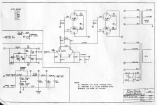
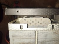
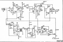
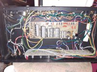
Here is some photos and what schematics I have, the original links in this thread are probably dead.
Shown in the photos:
It appears, that the power transformer has been changed at some point, though curiously the QC date is 1985. There are extra holes drilled the the chassis. It's taken years to notice that...
So in really need to measure voltages at all stages, although there are no hints of correct voltages on the schematics, I'll have to apply some common sense....
Also you can see the somewhat shoddy heater wiring, or wiring in general if I'm honest. I'd like to tuck that heater wiring up around the outside of the chassis, out of the way.
Also the browned board area is shown. This board is serial 550 056, which is referenced on the CD120 schematic
Recently I had some trouble with this amp and started this thread:
Tube head crackle and pop after warm up
Thanks for all the help and advice!
Well you can see that in all these years, I haven't got around to changing out all the suspect parts, caps, zeners.
Since I had some trouble with the amp and have gradually acquired most if the bits, I should do the job and document it here in the original thread. Daft as that seems, at least someone else may find it useful in the future, especially all the valuable contribution from others.
Here is some photos and what schematics I have, the original links in this thread are probably dead.
Shown in the photos:
It appears, that the power transformer has been changed at some point, though curiously the QC date is 1985. There are extra holes drilled the the chassis. It's taken years to notice that...
So in really need to measure voltages at all stages, although there are no hints of correct voltages on the schematics, I'll have to apply some common sense....
Also you can see the somewhat shoddy heater wiring, or wiring in general if I'm honest. I'd like to tuck that heater wiring up around the outside of the chassis, out of the way.
Also the browned board area is shown. This board is serial 550 056, which is referenced on the CD120 schematic
Attachments
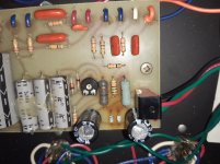
It looks like the 1k5 2W resistors are dropper/filters for the semiconductor analog electronics. They are likely to each pass about the same current (ie. voltage across them). If a semiconductor part fails then they could be heating up excessively, or the mains supply is a bit higher. Either way, best to raise new resistors off the pcb so that air can circulate, and the solder joint and pcb traces won't be at as hot a temp. Certainly make sure you reflow all the solder joints near that heat stress, as old solder joints that are heat stressed could cause problems.
Trobbins,
I plan to lift both these two resistors (marked 1W) and 18V zeners (again 1W), and replace with 2W devices, and elevate from the board surface as you suggest.
As far as the mains input, and suspected power trafo replacement at some earlier point in time, I have a couple of ideas for the future:
Use amplifier with isolation transformer (0-230-15: 230) to drop mains voltage to 230V average (my mains runs at 245V quite consistently)
Insert longer series chain of diode at the AC input to the PSU board (currently the amp uses 2 1N4007 in series, why? Do we need the PIV?) So it's possible I can lower the B+ a few volts this way and bring everything back into check (voltages UNDER the rating of electrolytics!!!)
I was looking back through the old thread and saw that you'd got a schematic from it. But when I look at the site now, it only has strings and no mention of amps or cabinets. Were they from the DeanMarkley.com site or somewhere else?
You're schematic might be a rarity now!
You're schematic might be a rarity now!
Yes originally the DM site had a support section, which lead to a repository of their amplifier schematics (its some time ago, so this is perhaps a flawed recollection)
At the time I couldn't find a schematic matching my amplifier, when DM support put me in touch with a contact, who informed me that these were developed from the CD60 CD120 and Spectra amps before that.
This chap pointed me to the schematics I have now. These got lost in several HDD failures, but a couple of hours googling and I found them again.
(Seems my original thread may have helped proliferate the schematic throughout the interwebs! Good thing for me or else I'd be stuck guessing)
I dind't read this thread completely, so I have to ask: Did you replace those coke bottle »6L6-GC's«? Due to their internal pinch stem construction they can't be real 6L6-GC's, but rather resemble older 6L6-G's with much lower dissipation ratings. If not done yet, replace at least those two by winged C SEC's, or J/J 6L6-GC's. Best would be to replace the whole bunch and keep the Philips EGC's as spares.
Best regards!
Best regards!
- Status
- This old topic is closed. If you want to reopen this topic, contact a moderator using the "Report Post" button.
- Home
- Live Sound
- Instruments and Amps
- Dean Markley T120-R fixer-upper project.