For your possible interest.
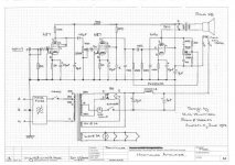
I have this amp on my bench for repair. The lady who brought it to me says it was her grandpa's Harmonica Amp and would like restored. Did a circuit trace. Very interesting tone control, treble boost/cut by feedback around the output tube. I looked up the tone control in RDH to find that the entire design is a 1942 W.N. Williamson design, Yep same Williamson who did the famous (well certainly the most copied) HiFi Amp design. Could have saved the circuit trace effort if I had know that up front.
6J7 triode mode to 6J7 pentode mode to 6V6 with an 80 rectifier. Lamp in standby switch line as a HT fuse.
Cheers,
Ian
Attachments
Last edited:


Finally got the old digital camera working.
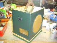
Here it is:
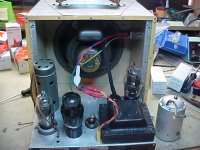
1st pic of the thing out of its case. The metal can along side the amp is the original home brew mains filter which just had to go. You can see in the 3rd pic that I just replaced it with an IEC Socket with an integral filter. The original mains input hole in the case was covered over with a brass plate. So where do you get a convenient brass plate for this? Any old hardware store - if you took the plate off you would see that the other side has engraved "NO ADVERTISING MATERIAL ACCEPTED -THANK YOU". That is it was intended for a mail box.
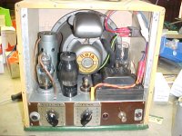
2nd picrture is of the amp back in its case, you can see that as well as replacing the mains input, I fitted an in-line mains fuse.
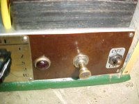
4th pic shows the "groovy" throtle knob standby switch. Pull out for standby.
The input 6J7 is in that shield at the rear left. The first thing I did for this amp was turf the 6V6GT and substitute the 6V6G ST shape tube (in the cetre).
All tubes tested good but have sent it back with a full set of spare tubes (2 x 6J7, 1 x 6V6G, 1 x 80).
Cheers,
Ian
Here it is:
1st pic of the thing out of its case. The metal can along side the amp is the original home brew mains filter which just had to go. You can see in the 3rd pic that I just replaced it with an IEC Socket with an integral filter. The original mains input hole in the case was covered over with a brass plate. So where do you get a convenient brass plate for this? Any old hardware store - if you took the plate off you would see that the other side has engraved "NO ADVERTISING MATERIAL ACCEPTED -THANK YOU". That is it was intended for a mail box.
2nd picrture is of the amp back in its case, you can see that as well as replacing the mains input, I fitted an in-line mains fuse.
4th pic shows the "groovy" throtle knob standby switch. Pull out for standby.
The input 6J7 is in that shield at the rear left. The first thing I did for this amp was turf the 6V6GT and substitute the 6V6G ST shape tube (in the cetre).
All tubes tested good but have sent it back with a full set of spare tubes (2 x 6J7, 1 x 6V6G, 1 x 80).
Cheers,
Ian
Attachments
Last edited:
Ian,
As a correction, RDH4 figure 15.35b refers to reference 67 which is the June 1942 R&H article by W.N. Williams (not Williamson), and based on Radiotronics articles. An earlier R&H Dec 1941 article is a reprint from Radiotronics. The recommended operating conditions for a triode connected 6J7 is with 5k cathode, 100k anode and about 4V bias.
I'm pleased I found your thread on the 6J7 as I'm just restoring a 1940's amp with 3x 6J7s operating triode mode. The amp used 3k2 bypassed cathodes, but I'm changing to 4k7 and will try and keep B+ around 250V.
Ciao, Tim
Tim,
Thanks for the correction on the schematic source.
I'm also working on a historic Church PA amp which is pentode mode 6J7 preamps for "pick-up" and microphone channels, triode mode 6J7 to drive an interstage / phase spliitting transformer and a pair of push pull 807. Biggest bug bear at the moment is the 50 Ohm Output but I've managed tio get hold of a vintage A&R matching auto-transformer rated at 100W which has 100V, 70V 50 ohm, 16 ohm, 8 ohm, 4 ohm and 2 ohm connections which I will fit inside the thing. I've done a circuit trace. Will check on the 6J7 operating points and report back.
Is there anyware that has the Radiotronics articles on-line?
I'm currently chasing a local guy who is reputed to have a set of 10 CDs with a scan of all of Radio TV and Hobbies (in its various incarnations) covering 50 years or so (he is the President of the local vintage radio society and I vaguely recall being in the same class as him as a first year Radio Trade apprentice in 1973, just as I vaguely recall us getting "chatted" by the police when we went out for a spin in his Triumph Herald).
Cheers,
Ian
I'm currently chasing a local guy who is reputed to have a set of 10 CDs with a scan of all of Radio TV and Hobbies (in its various incarnations) covering 50 years or so
Silicon Chip magazine has a DVD available, with scans of every copy of RTV&H from April 1939 to March 1965.
Books - Silicon Chip Shop - Silicon Chip Online
Guys,
The local "Hysterical" Radio Society to the rescue with a useful index.
http://www.hrsa.asn.au/hrsa-files/ea-rth-index-090512.pdf
Cheers,
Ian
The local "Hysterical" Radio Society to the rescue with a useful index.
http://www.hrsa.asn.au/hrsa-files/ea-rth-index-090512.pdf
Cheers,
Ian
Last edited:
For your possible interest.
I have this amp on my bench for repair. The lady who brought it to me says it was her grandpa's Harmonica Amp and would like restored. Did a circuit trace. Very interesting tone control, treble boost/cut by feedback around the output tube. I looked up the tone control in RDH to find that the entire design is a 1942 W.N. Williamson design, Yep same Williamson who did the famous (well certainly the most copied) HiFi Amp design. Could have saved the circuit trace effort if I had know that up front.
6J7 triode mode to 6J7 pentode mode to 6V6 with an 80 rectifier. Lamp in standby switch line as a HT fuse.
Cheers,
Ian
I'm going with the THd Univalve modded similar to your 1942 but adding a pentode(screen/suppressor linked/triode mode) front end.
That is a nice unit schematic, shows someone loved it.
-
> scan of all of Radio TV and Hobbies
{much later}
American(!) Radio History has part of 1939 to 1947:
RADIO & HOBBIES; Australian hobbyist magazine
W.N. Williams article:
http://americanradiohistory.com/Archive-Radio-and-Hobbies/40s/Radio-and-Hobbies-1942-06.pdf --page 21 of 5MB PDF
{much later}
American(!) Radio History has part of 1939 to 1947:
RADIO & HOBBIES; Australian hobbyist magazine
W.N. Williams article:
http://americanradiohistory.com/Archive-Radio-and-Hobbies/40s/Radio-and-Hobbies-1942-06.pdf --page 21 of 5MB PDF
Long-time lurker, first-ish time poster.Ian,
As a correction, RDH4 figure 15.35b refers to reference 67 which is the June 1942 R&H article by W.N. Williams (not Williamson), and based on Radiotronics articles. An earlier R&H Dec 1941 article is a reprint from Radiotronics. The recommended operating conditions for a triode connected 6J7 is with 5k cathode, 100k anode and about 4V bias.
I'm pleased I found your thread on the 6J7 as I'm just restoring a 1940's amp with 3x 6J7s operating triode mode. The amp used 3k2 bypassed cathodes, but I'm changing to 4k7 and will try and keep B+ around 250V.
Ciao, Tim
Thanks to all for sharing this knowledge. I had a bunch of 5693/6SJ7 sitting around and decided to give this amp a shot.
With a pile of 5K SE transformers in a box elsewhere, I'm slightly unwilling to trim the 125ESE lead wires for now. Also should have rotated pretty much every socket 45-90 degrees differently than I did, and the reversed N-68X PT only puts out about 255VDC B+ under load. Also, if I'd known that triode-strapped 6J7/6SJ7 is practically a 6C5/6SN7, I might have just used a 6SN7 or Broskie's buffered screen feedback. That aside, the tone control and amp play quite nicely through a sealed 2x12 with humbuckers. No field coil speaker involved, and no high B+ to spare, so I used a 6H/150R choke + 68uF in a CLC for filtering.
Quite a neat little amp. I may build another and/or swap the PT for a beefy 265VAC + 12VAC transformer I have, and swap the 6V tubes for 12SJ7/12V6.
I found a later April 1942 issue of "Radio & Hobbies" that referenced the tone control. Full B
- Home
- Live Sound
- Instruments and Amps
- Historic Harmonica Amplifier