Hi,
I'm looking at a Fender Super Reverb circa 1970, which has had its original power supply transformer replaced. The replacement transformer, a locally made item, appears to be possibly twenty or more years old - the company that manufactured it is well and truly gone. It has a primary winding rated for 240 VAC and a secondary winding of 175-0-175 VAC @ 145 mA, well below the Fender original 360-0-360 VAC.
Could there be any practical reason why this amp might be fitted with this transformer, (apart from the fact that it might have been the only option available at the time). Is it even possible to properly bias the valves under these conditions?
Any comments are much appreciated,
The only thing I can think of is if they had the power supply double the voltage it may work okay.
Voltage Multipliers
You'd see some capacitors and diodes added. That amp probably sounds pretty bad in it's current state .
.
Voltage Multipliers
You'd see some capacitors and diodes added. That amp probably sounds pretty bad in it's current state
.
Last edited:
thanks defec, - there's nothing I can see in the way of voltage doubling. The rectifier tube is gone and a bridge rectifier has been added, from there on in it looks fairly original. The amp has been used regularly and 'sounding good' until only recently having developed some problems.
Perhaps a lower HT, like a saggy HT, would introduce power amp distortion earlier?
That's the only thing I can think of, but I'd see if a "correct" transformer can be found: restoring the amp to its original specification seems wiser than running it in a way it wasn't designed for.
Chris
That's the only thing I can think of, but I'd see if a "correct" transformer can be found: restoring the amp to its original specification seems wiser than running it in a way it wasn't designed for.
Chris
Chris - I think the 'correct' replacement transformers aren't too hard to come by and it would be good, as you say, to run the amp as was designed. That being said I'm kind of curious to know what the guy was up to who fitted the replacement.
@Enzo to my surprise B+ is 500VDC.
@Enzo to my surprise B+ is 500VDC.
Hi jjman, to confirm: 500VDC, tubes installed and in play mode. The PT does not get hot in playmode.
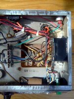
To widen the picture a bit, there is another foreign object in the chassis which I assume is a small transformer/rectifier to supply the bias voltage as it likely this wasn't available from the main power transformer. One side is connected to line voltage at the fuse holder and power switch with the other side being connected to the bias circuit alone.
The PT transformer secondary wires, labeled (correctly?) 175 VAC connect directly to the bridge rectifier which connects to the original standby switch and power supply filtering.
Well, regardless of the theory behind it, it works. And in the interests of learning stuff about the amp a bit of mystery can be a good thing.
Thanks for your ideas, everyone. Anymore thoughts are welcome!
Attachments
OK, so it is labelled 175v, but you are getting full B+ voltage. SO there is no "problem", this is just a matter of interest. Fair enough.
It has a 240v primary, but is there any chance the mains are actually wired to the primary configured for 120v operation, which would double the secondary voltages when 240v was applied to that? 350-0-350 would net you about 500VDC when rectified and filtered.
It has a 240v primary, but is there any chance the mains are actually wired to the primary configured for 120v operation, which would double the secondary voltages when 240v was applied to that? 350-0-350 would net you about 500VDC when rectified and filtered.
I can't be sure, but there's every chance that this, or closely related, must be the case and it's as good an explanation as I could ask for.
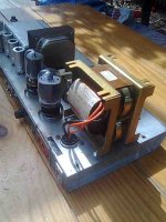
There must be some adaption of the PS transformer because it doesn't seem necessary to use such a heavy gauge wire, (the orange leads seen in picture), on the secondary for the heater supply. I would expect to see this gauge wire used on the primary side.
There must be some adaption of the PS transformer because it doesn't seem necessary to use such a heavy gauge wire, (the orange leads seen in picture), on the secondary for the heater supply. I would expect to see this gauge wire used on the primary side.
Last edited:
Actually, wire size is about current, not voltage, and the heaters are the highest current draw in the amp. I normally expect the 6VAC winding to be the heaviest wire.
Exactly, the thickest wire is going to be the heater ones, as that's the highest current - as shown by the thickness of the windings on the transformer.
- Status
- This old topic is closed. If you want to reopen this topic, contact a moderator using the "Report Post" button.
- Home
- Live Sound
- Instruments and Amps
- Fender low voltage power supply