Hello. Here is my problem. I'm trying to build a tube amp for my bass guitar. When no gnfb is applied it works fine. I have no scope but I'm using sound card and couple of DMMs for measurements, what makes me blind in region above 20kHz.
So, here is open loop response(it is quite flat with 0.5 dB variation):
(gain), (phase) @ (freq)
25.1dB, +19 Deg @ 10Hz
25.9 dB, -40 Deg @ 20kHz
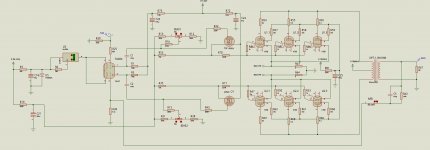
When I apply gnfb, as shown on schematics, is oscillates with distorted sound as soon as input voltage crosses 120-150 mV point.
Then I started tweak some parts in different combinations with no success:
output tubes: increase screen resistors from 150R to 1K, increase grid stoppers from 1K to 22K, solder 2pF, 3kV capacitors from anode to cathode.
Phase inverter tube: solder 100-200pF HF-roll-off-capacitor across anodes of two triodes, increase grid stopper to 150k(seems helps a little)
Increase freq correction capacitor in gnfb loop to 200pF, which limits close loop HF response to 10Khz.
I need some new thoughts.
Thanks!
So, here is open loop response(it is quite flat with 0.5 dB variation):
(gain), (phase) @ (freq)
25.1dB, +19 Deg @ 10Hz
25.9 dB, -40 Deg @ 20kHz
When I apply gnfb, as shown on schematics, is oscillates with distorted sound as soon as input voltage crosses 120-150 mV point.
Then I started tweak some parts in different combinations with no success:
output tubes: increase screen resistors from 150R to 1K, increase grid stoppers from 1K to 22K, solder 2pF, 3kV capacitors from anode to cathode.
Phase inverter tube: solder 100-200pF HF-roll-off-capacitor across anodes of two triodes, increase grid stopper to 150k(seems helps a little)
Increase freq correction capacitor in gnfb loop to 200pF, which limits close loop HF response to 10Khz.
I need some new thoughts.
Thanks!
Attachments
What kind of oscillation? HF? LF? ELF?
For a Guitar amp you don't need 20-20KHz response, and limiting it to 10KHz is probably a good idea any way. Decrease your coupling caps in the first stage (C1, C2) to rolloff more LF. -f3 at 60Hz is probably good unless you are doing bass guitar.
For a Guitar amp you don't need 20-20KHz response, and limiting it to 10KHz is probably a good idea any way. Decrease your coupling caps in the first stage (C1, C2) to rolloff more LF. -f3 at 60Hz is probably good unless you are doing bass guitar.
Have you tried reversing the OPT primary leads. Sounds like you're out of phase. This is probably the most common cause of oscillation with a new build.When I apply gnfb, as shown on schematics, is oscillates with distorted sound as soon as input voltage crosses 120-150 mV point.
if I do this, it oscillates even when output tubes just start to conduct first few mA, so I hope I'm in phase right nowHave you tried reversing the OPT primary leads. Sounds like you're out of phase. This is probably the most common cause of oscillation with a new build.
I'd say you need some fairly heavy "lag" compensation across the plates of the input stage, and you really, really need an oscilloscope to be able to see how effective this is.
I would place an RC network across the plates of the 12AX7A, set the pole around 20kHz to start with the zero tbd.. You could even just start with 100pF and 10K and work from there. Proceed with caution, and make sure the OPT is loaded properly.
Hopefully the 12AX7 is not wired per schematic as the pin out shown is wrong.. See http://www.mif.pg.gda.pl/homepages/frank/sheets/127/1/12AX7A.pdf
Triode 2 [Plate 1, Grid 2, Cathode 3], Triode 1 [Plate 6, Grid 7, Cathode 8]
Get rid of the parallel cap in the feedback loop as this increases feedback as the frequency increases - just what you don't want to do. There are very specific cases where this works in conjunction with the rest of the compensation and specific HF complementary phase shifts in the OPT. More often than not it seems to cause problems. I've generally found that modest feedback ratios (20dB of feedback or less) and simple lag compensation are usually enough for stability. A zobel across the secondary can sometimes help as well.
 I'm also going to move this to I&A per forum directive since this is a bass amp.
I would place an RC network across the plates of the 12AX7A, set the pole around 20kHz to start with the zero tbd.. You could even just start with 100pF and 10K and work from there. Proceed with caution, and make sure the OPT is loaded properly.
Hopefully the 12AX7 is not wired per schematic as the pin out shown is wrong.. See http://www.mif.pg.gda.pl/homepages/frank/sheets/127/1/12AX7A.pdf
Triode 2 [Plate 1, Grid 2, Cathode 3], Triode 1 [Plate 6, Grid 7, Cathode 8]
Get rid of the parallel cap in the feedback loop as this increases feedback as the frequency increases - just what you don't want to do. There are very specific cases where this works in conjunction with the rest of the compensation and specific HF complementary phase shifts in the OPT. More often than not it seems to cause problems. I've generally found that modest feedback ratios (20dB of feedback or less) and simple lag compensation are usually enough for stability. A zobel across the secondary can sometimes help as well.
I'm also going to move this to I&A per forum directive since this is a bass amp.I don't know if this will help, as most of my amps have been solid state. But I have on at least a few occasions ended up with a situation where feedback that was SUPPOSED to be out of phase (negative feedback) was actually becoming in-phase positive feedback at some ridiculous frequency, which fortunately I've always had the benefit of seeing on a scope. One thing that has gotten me out of the bind has been adding a series inductance, which I've usually ended up winding myself, to make my feedback path a higher Z at those frequencies. In my case the oscillation frequencies would usually surprise me, being up over 1 mHz, which made it reasonably easy to come up with an inductance that solved the problem without affecting the audio range. In fact if your lucky, the series L could create enough of a phase shift at the troublesome frequencies, that you might hardy need anything at all.
By the way, even if all that advise is nearly useless for you, I really feel for anyone trying to design amplifiers without some kind of scope. I think I still have an old B&K dual trace that I'd offer you at a very reasonable cost. It might cost a bit to ship the stupid thing, but feel free to contact me directly if you think you might want it. i believe its good to 20Mhz.
By the way, even if all that advise is nearly useless for you, I really feel for anyone trying to design amplifiers without some kind of scope. I think I still have an old B&K dual trace that I'd offer you at a very reasonable cost. It might cost a bit to ship the stupid thing, but feel free to contact me directly if you think you might want it. i believe its good to 20Mhz.
So, I finally get it stable with fairly high freq correction on first tube. All my problem was open loop distortion caused by soldering error not feedback issue.
Thanks for every one")
Thanks for every one
I'm very thankful for your suggestion but shipping cost oversea would be a deal-breaker for meBy the way, even if all that advise is nearly useless for you, I really feel for anyone trying to design amplifiers without some kind of scope. I think I still have an old B&K dual trace that I'd offer you at a very reasonable cost. It might cost a bit to ship the stupid thing, but feel free to contact me directly if you think you might want it. i believe its good to 20Mhz.
- Status
- This old topic is closed. If you want to reopen this topic, contact a moderator using the "Report Post" button.
- Home
- Live Sound
- Instruments and Amps
- help with oscillation problem - bass amp