Many years ago I had built up a perfboard based on an MXR Distortion Plus circuit and was pretty satisfied with the sound. But the enclosure was not too practical to bring along to practices or shows. I was recently on a thread here on DIY Audio that was discussing different distortion circuits, using transistors in the op-amp feed-back loop, LED clipping, hard /soft clipping etc. Based on that, I decided to use this circuit as a base and build up a pedal that I could more easily modify the circuitry and explore some different techniques and hopefully interesting sounds.
FYI Here is a link back to the original topic thread.
http://www.diyaudio.com/forums/inst...stors-op-amp-feedback-loop-4.html#post2766382
As I go along I will post some pictures and schematics, feel free to send comments and/or suggestions, as it will be a work in progress.
FYI Here is a link back to the original topic thread.
http://www.diyaudio.com/forums/inst...stors-op-amp-feedback-loop-4.html#post2766382
As I go along I will post some pictures and schematics, feel free to send comments and/or suggestions, as it will be a work in progress.
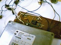
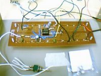
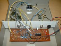
Here are some pics of the perfboard circuit. I decided to use a larger enclosure than the more standard Hammond cast aluminum type. I had an unused case in sheet steel that was bigger so I could easily make mods as I go..one thing though: the sheet metal is not as rigid so I installed an aluminum plate over where the foot-switch goes to spread out the force when pressing it. Looks a bit different, but works OK
Attachments
First modifications from original circuit:
1-Installing a DPDT footswitch in place of original SPDT for true bypass of the effect board.If all goes well on the build I plan to change it to a 3PDT to put an LED for active/bypass indication.
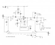
2-Original MXR circuit uses a pair of Germanium diodes (IN270) for symmetrical clip located at the output of the op amp circuit. That type of post op-amp circuit is considered ''hard clip'' type at least for purposes of discussion. The forward drop on this pair is 0.310 and 0.312 volts and has a more rounded switching curve than silicon, but clipping at lower voltage so not much headroom.
I jumpered some wires in there so I can switch select from the stock pair to a non-symmetrical type post op amp clipping.
3-Another switch will be added to select from hard clipping (post op amp) to a soft clipping circuit within the op-amp NFB loop.
4-Future addition of a tone control, as the original MXR Dist + only had gain and level pots.
1-Installing a DPDT footswitch in place of original SPDT for true bypass of the effect board.If all goes well on the build I plan to change it to a 3PDT to put an LED for active/bypass indication.
2-Original MXR circuit uses a pair of Germanium diodes (IN270) for symmetrical clip located at the output of the op amp circuit. That type of post op-amp circuit is considered ''hard clip'' type at least for purposes of discussion. The forward drop on this pair is 0.310 and 0.312 volts and has a more rounded switching curve than silicon, but clipping at lower voltage so not much headroom.
I jumpered some wires in there so I can switch select from the stock pair to a non-symmetrical type post op amp clipping.
3-Another switch will be added to select from hard clipping (post op amp) to a soft clipping circuit within the op-amp NFB loop.
4-Future addition of a tone control, as the original MXR Dist + only had gain and level pots.
cant you use a DPDT and just switch the source for the output? isn't it still true bypass, but both inputs are connected at the same time, used it alot with success. i also found that some serious bass rolloff gave quite good results (6db cut at 2k) but needs a fair boost at the end. any schematics for what you've done?
Hi Razorrick,
Sure, agree it does work to leave both inputs connected, just as with original MXR circuit that I had, but in that bypass arrangement you have the source signal going to the input impedance of this circuit always in parallel with the impedance of next element or elements(amp, another pedal effect). If you have a few effects all bypassed that way it could seriously degrade signal. I say ''could'' because it depends on all the individual effects, their input impedance and bypass modes.
When manufacturer's specs say ''true bypass'' they refer to the bypass as completely switching out the effect from the signal chain at both input and output. Most of the early pedals did not have true bypass, it cost a little bit more money to put in there. My DOD 250 had a SPDT with no LED indicator either. IMO if you find that the straight guitar signal sounds weak when a lot of pedals are plugged in and bypassed, you could look at adding true bypass to them to restore the signal. When I get the mods installed and checked I will post a schematic.
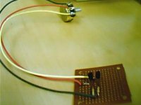
The SPDT footswitch I am using is Miyama type. A lot of people use the Carling type, I find the Miyama to be really solid and reasonable price (about $9 CDN)
An externally hosted image should be here but it was not working when we last tested it.

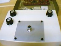
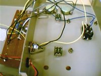
front panel wiring
DPDT footswitch is installed and wired per previous diagram with in/out 1/4'' jacks. 9VDC adaptor power jack mounted and wired, not using battery connector on this build. FYI on most commercial 2.1 mm jacks for powering pedals, the polarity is negative on pin and positive on barrel. Some advice: use the insulated type jack that won't short to the case, as the case is referenced to negative. Double check to make sure your adaptor is polarized correctly before power up.
DPDT footswitch is installed and wired per previous diagram with in/out 1/4'' jacks. 9VDC adaptor power jack mounted and wired, not using battery connector on this build. FYI on most commercial 2.1 mm jacks for powering pedals, the polarity is negative on pin and positive on barrel. Some advice: use the insulated type jack that won't short to the case, as the case is referenced to negative. Double check to make sure your adaptor is polarized correctly before power up.
Attachments
Tested the hard clip mod with a green LED at about a 2V clip, in parallel with one stock 1N270.
The sound opens up much more dynamically than the stock MXR circuit, and I do like the asymmetric clip..I wouldn't say exactly ''tube like'', but going more in that direction of sound. (I tested on a Traynor transistor guitar amp, the clean channel which does not color the sound too much).
The sound opens up much more dynamically than the stock MXR circuit, and I do like the asymmetric clip..I wouldn't say exactly ''tube like'', but going more in that direction of sound. (I tested on a Traynor transistor guitar amp, the clean channel which does not color the sound too much).
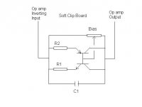
Soft Clip Board
Hi Razorrick, Yes I would like to be able to adjust the symmetry (or asymmetry) of the NFB signal as a control pot on the modded pedal. This is the first schematic, and from there it is possible to try different combinations of transistors (including FET type). The C1 will be a 10 pF just to keep out potential oscillations. I may try some caps in parallel with R1 and R2, or tied in somehow to the bases of the transistors to play with the frequency response of the clipping.interesting build, just wondering, what is the bias for on the soft clipping board? im guessing to fine tune clip symmetry?
Attachments
mosfet clip
Thank you for suggesting it. I am definitely interested in trying that as well..especially on the soft clip NFB circuit. I am wondering if I would need to put a limiting resistor at the gates, or is it possible in this to tie directly to their sources?an alternative to clipping diodes - try mosfets with the G&S tied together
- Status
- This old topic is closed. If you want to reopen this topic, contact a moderator using the "Report Post" button.
- Home
- Live Sound
- Instruments and Amps
- Distortion pedal build