Mosfet internal diode
Hi Razorrick, I believe that for mosfets the internal diode is intrinsic to the construction of that type of device, so for mosfets at least I don't think you could get one without it. That was the funny thing about some of the commercial products touting that they are using mosfets for clipping, in reality most of them were not even using the G-D connected diode connection for clipping(!) the signal routes through the SI internal diode as it has the lower threshold than the GD diode..but saying that it sounds better than a standard Si diode may be true, the internal diodes are a little slower (spongier?) to clip..
There are, I think some workarounds to that issue with mosfets that I will try out.
DPDT footswitch is installed and wired per previous diagram with in/out 1/4'' jacks. 9VDC adaptor power jack mounted and wired, not using battery connector on this build. FYI on most commercial 2.1 mm jacks for powering pedals, the polarity is negative on pin and positive on barrel. Some advice: use the insulated type jack that won't short to the case, as the case is referenced to negative. Double check to make sure your adaptor is polarized correctly before power up.
hi shanx, newb here just blowing thru some threads to get a feel for the forum and this was the first i landed on...lucky you!
")
if you're gonna run this with other pedals in the future, particularly on stage, you may run into some problems with your mains wiring...get a lot of noise and garbage...particularly as dirt pedals are usually high gain and first in line.
my humble suggestion would be to add a simple network to your power supply...you can wire it right to the 2.1mm power jack if need be...
use an 1n400X diode, with the band pointing to B+ in parallel with a 100-470u cap wired the same way...you can have the band on the cap denoting the negative side go directly to the negative terminal, and the positive to the positive terminal of the jack if need be. this will help filter mains noise and hum out...if need be, a small resistor in series (100-330r) with the b+ can also help if needed.
i find without the extra stage of filtering on power supplies in guitar pedals, particularly dirt pedals, that the pedal can be subject to a lot of unwanted and unnecessary noise. this can help.
that said, looks like a cool design, well done mate!
Been a while since I posted. I was looking into tying G and D together on the mosfets I have using them as 'diode' configuration, and this has been done in some commercial design stuff. There are some issues, because a mosfet example 2N7000 like others has an internal connected body diode. In some , but not all, commercial mosfet clipping designs the clipping circuit (with paralleled diode connected mosfets) the signal ends up only being clipped by the internal Si body diodes (!) and not even using the Mosfet 'diode' circuit. They even add Ge diodes in series to soften out the clip. Well that is something to consider.
I am going to pursue some of my own ideas on this now.
i believe the entire reason for using mosfets as diode clippers is precisely to take advantage of the internal diode's clipping mate. again, i'm a newb, so pardon if i'm off base here.
Hey all,
Sorry been a while since posting..as life tends to send lots of other tasks our way.
Pinkjimiphoton, you are right that internal body diodes in the mosfet based distortions are used in fact as diode clippers. For the most part, the commercial designs tend to state that they are using diode connected (G and D tied together) mosfets to get the ''soft distortion'' from the mosfets. Their claims are not exactly true(!) But hey maybe it is the creative marketing departments..I was just pointing out that fact for people to look closer at. Thanks for bringing it up and confirming it. Your filtering comments for the Power supply are very welcome too. I am using a well regulated DC supply powering 5 or 6 pedals, and so far no big problems. Those small plug-type AC adaptors are indeed very noisy, with no DC regulation.
In the meantime on the build I am doing for a friend I started working on some minor improvements:
2 footswitches, one is bypass for the whole pedal and the other one to select between the soft clip in the NFB loop, or the diode clipper circuit at the output.
I installed a DIP switch on the board to be able to select various combinations of clipping elements. Stock Ge, LED, and Mosfet.
Reverse polarity protection
I pretty much always put this in, usually as a schottky type diode in series in the power feed, so as to protect against wrong-way-round wall warts and battery connection.
I've even fitted it to a cheap chinese 5 band graphic eq pedal. The pcb had a position for it, nicely silk screened, with a wire link inserted instead - presumably to reduce production costs.
You can do it with a mosfet too, for just about zero volts drop, see RG Keen's site:
Advanced Power Switching and Polarity Protection for Effects
Oh no, I'm now back in the infinitely expandable world of distortion effect design.........
Diode protection and power filtering
Hi Pinkjimiphoton and Simon,
Thanks for the suggestions on improving the power supply.
On this build I installed a 1n4007 protection diode across the rails. Diode is normally reverse bias when supply is correct. If the polarity is reversed it will shunt through..probably would toast itself if left for too long. I installed off the board, it is directly at the power jack. Also added 100 Ohm then 47uF as additional filtering before the hitting the supply rails.
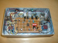
I point to point wired this thing on perfboard and with the additional filtering it is really quiet, right up to full gain. I ran a solid bare copper wire across the bottom of the board for the ground rail. All the ground runs, kept separated in the circuit are soldered directly to it.
Hi Pinkjimiphoton and Simon,
Thanks for the suggestions on improving the power supply.
On this build I installed a 1n4007 protection diode across the rails. Diode is normally reverse bias when supply is correct. If the polarity is reversed it will shunt through..probably would toast itself if left for too long. I installed off the board, it is directly at the power jack. Also added 100 Ohm then 47uF as additional filtering before the hitting the supply rails.
I point to point wired this thing on perfboard and with the additional filtering it is really quiet, right up to full gain. I ran a solid bare copper wire across the bottom of the board for the ground rail. All the ground runs, kept separated in the circuit are soldered directly to it.
Well, why not connect the diode downstream of that 100R resistor?
That way if you do connect up the wrong way it's much less of a fight between your diode, and those in the psu.
The way you've got it at the moment, either your diode (rated at 1A) fails and then the effect with it, or your psu fails. They don't normally have a resettable fuse, if they have one at all....
It would need to be a 1W resistor though.
Yeah, I could've done it that way. And come to think of it, if I leave the 100 ohm at a lower power rating it should be the first to blow and open the circuit (good thing?)
Well that's one way of looking at it!Except that then the pedal isn't working til you replace the resistor.
Put the diode in series, and hey presto, plugging in the wrong wall wart breaks nothing - fantastic eh?!
He He, yes I was kind of making fun of my own train of thought there!
Seriously I have seen this in commercial and industrial electronics: protection diodes put in that way to clamp across the rails. Keeps the service department happy cause they can change out a 10 cent component and charge $$ for non-warranty work.
I will probably get around to changing with a schottky in series for low voltage drop, cause I am doing this for a friend. I know his pedal board is wired right for the power supply, I got him the supply and wired the DC plug myself. But you never know, if he grabs another wall wart he could be in trouble!!
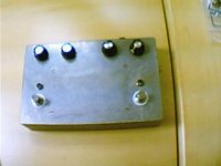
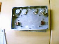
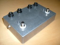
2nd build pics
Here are some better pics of the 2nd build. I tried to keep the wiring as neat as I could on this one. Going to prime the case and my friend will apply the paint and clear coats.
All the point to point wiring was a lot of work. If I get asked to do more I will have to get some circuit boards done. This one still has some room left if he wants me to add anything else.
Attachments
Hi Shanx,
Looking good. Nice proportions for stompability.
If you're going to paint it, maybe just deepen the countersinks a little bit. I have no magic solution to getting that one right first time, just give it my full attention and work with one of the screws I'll be using in my left hand, trying the head for fit upside down, so as not to have to poke the threaded portion through. If I don't make it easy to try it often.....
Looks very reconfigurable too, I like the secret toggle switch. Those little DIP switches are a type of slider switch, so a bit prone to oxidation in the long term. One alternative is to use computer style jumpers, three pins per jumper, so unused ones are still securely on two pins.
The metal LED bezels look up to the job too, think I'll look out for some of those, have had plastic collar mounted ones pushed in slightly in use.
Very tidy. I hope your friend appreciates your hard work.
Last edited:
Hi SimonB and Razorrick
I appreciate the feedback alot. I did deepen the countersinks a bit before shooting the box with 2 coats etching primer. My friend builds guitars and he will probably fill in the screw supports before he sprays final coats of paint. He is setup to spray nitro lacquer finishes (he does beautiful work!) I did some retro graphics and they will get applied before clear coat. He is putting on chrome telecaster knobs on the controls.
He is appreciative and he has done a lot of great service work for me on my guitars.
You guys on DIY have done some really great work..so I was inspired to neaten up my wiring for this second build. My first build on this thread basically a working proto to play with.
The basic schematic for this is at the beginning of the thread. For the postclip part, I just installed different diode combinations and socket for mosfets wired as diodes (G-S tied together. The DIP switch replaced the test diode switch. Simon, the jumper idea is cool..maybe on next one..because I need to get this one delivered.
Alas, the stealth switch is now placed up top..I kinda like it buried in the box too!
That switch is to add a boost and is just playing with the NFB resistance.
I will post some sound clips shortly
- Status
- This old topic is closed. If you want to reopen this topic, contact a moderator using the "Report Post" button.
- Home
- Live Sound
- Instruments and Amps
- Distortion pedal build