I'm thinking about buying the hall amplification vvr kit to replace the attenuation circuit in my ac4tv. I haven't done any amp building or modding before, and I'd like to try and make sure I can figure out how to wire it before I place the order. I know that there are the connections that need to be made; to B+ in, B+ out and ground. I can handle the ground connection, but I'm wondering, if I post a schematic of the amp, can anyone help me locate the other two circuit points? I think if I know where they are on the schematic, I'll be able to find them on the board. Thanks!
Thanks! Here's a link to the schematic: http://website.lineone.net/~m0dzo/AC4TVschem.pdf
And here's a link to the thread that got a few people working on putting it together: Vintage Amps Bulletin Board • View topic - AC4TV schematics anyone?
I was thinking about this more as I was falling asleep last night and I think I have a little better understanding of how the whole thing is supposed to work. And it leads me to a few questions/statements I'd like to submit just to get your thoughts.
1) I believe that the kit can be installed to scale the B+ voltage for both the preamp and the power amp sections of the amplifier OR it can be applied just to the power amp section. I think installation is easier when it's applied across the whole amp. What would be pros/cons tone-wise or control-wise to one method over the other?
2) The installation that I saw online used the lugs on the standby switch for a B+ in and B+ out. It's convenient because the B+ power rail is already interrupted by the switch. This would scale both preamp and power amp sections?
3) My amp does not have a standby switch. If I want to scale the whole amp is there another means to get the VVR into the B+ in series without cutting traces and drilling holes on the circuit board? (I'm not opposed to trying this, just wondering)
4) If I want to scale just the power amp it seems to me that I have to interpose the VVR somewhere on the node common to R16, R19 and pin 9 of the EL84. Is that correct? Is that likely to require cutting a trace and drilling holes? How big a deal is that?
Thanks so much!


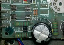
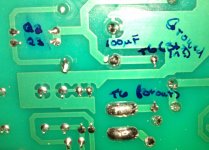
Okay, so I located the relevant part of the circuit board and I think I have an idea of where to solder in the VVR. If you look at the of the front of the board, the lug labeled "Tag 6" is the spot where the wire from the OT primary attaches. ("Tag 4" is the other end of the primary that runs to the anode of the EL84.) There's a jumper from the T6 lug to the node shared by R16, Q2, Q3 and the 100 uf cap. In the photo of the back of the board I have the lug side of that jumper labeled "T6 (B+ out)" and the other end of the jumper labeled "T6 (B+ in?)" I also labeled the locations of the two diodes and the big cap for reference.
Can I take the jumper out, and wire in the VVR in its place?
Can I take the jumper out, and wire in the VVR in its place?
Attachments
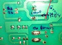
Nevermind... I see that that would put R16 on the wrong side of the VVR. So...on the photo of the back of the board, the solder connection in the upper right corner is one side of R16.
What if I drill a hole just to the left of that R16 solder joint. Then I remove the jumper that's there (between the points I have labeled as B+ in and B+ out) and instead jump from the T6 lug to the new hole next to R16, then solder the B+ out right to the T6 lug? Then I cut the trace to the left of the hole I drilled and use the point labeled as"T6 (B+ in?)" for B+ in?
Or is it okay/better to disconnect the end of R16 from the board and solder a jumper right to the free end of R16 and to the lug at T6 and solder the B+ out to the same lug?
Great! Got it.
One last thing. Do I need to worry about the kind of wire I use to make that connection?
I can scavenge pieces that were used to hook up the attenuator network after that's removed. Is there any reason that those wouldn't be suitable? Proper voltage rating would be the concern for that part of the circuit right?
Last edited:
Vincenz - I sent a PM, but I remembered that I didn't end up doing the mod exactly as Nigel recommended. I think my method is equivalent though. You can see what I did with pics here:
http://www.sewatt.com/node/19662
I think you need to register an account to look at content there.
http://www.sewatt.com/node/19662
I think you need to register an account to look at content there.
@clengman: I am going to make the same mod on my 4TV. Very interesting topic with very useful informations.
Anyway, did you finally modify your amp? Does it work fine?
Vincenz - since you said you were having a little trouble registering on sewatt.com, here's a pic of the mod the way I did it, and what I posted on the forum:
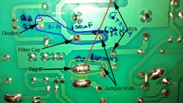
I've attached a photo of the front of the board for reference and a photo of the back of the board that's marked up with my proposed installation. This is what I'm planning to do:
1) Remove the jumper that connects Tag 6 to the trace connecting the diodes, the first filter cap, and R16.
2) Make a cut in the trace at the white line just above the diodes.
3) Connect a jumper (red line) from R16 to "Tag 6."
This should divide what was previously one node (the diode output/OT input trace) into two separate nodes for B+ OUT and B+ IN as I have them marked in my photo. It also leaves two vacant holes in the PCB that can be used to solder in the VVR.
It's working fine.
Attachments
Hi @pwing @clengman
I'm thinking about adding VVR to my AC4TV and discovered your post about you adding it to yours.
AmpMaker.com supplies the kit which I *think* I can probably put together, even with my limited soldering experience (ie resoldering the connections on a Tele selector switch and jack - and that's it!). But I doubt that I'd be able to install the new circuit into the amp itself as I cannot read - or be confident that I could learn accurately how to read - a circuit diagram. So I'd like to ask you some advice...
- How difficult was the installation?
- Is there some sort of step-by-step installation guide out there?
- And finally, was it worth it - were you happy with the results?
- Status
- This old topic is closed. If you want to reopen this topic, contact a moderator using the "Report Post" button.
- Home
- Live Sound
- Instruments and Amps
- Hall VVR in an AC4TV