the 4D32 uses the same sockets as 839B, 832A, and 6C33....
Ok, Tony, thanks!
We call these sockets Septar on our side of the Atlantic, and yes, they're still available...
Another point: An output power of about 120 watts can also be expected from a pair of 6KG6A/EL519/40KG6A/PL519 tubes, running at about 420 volts and driving a load of about 1400 ohms. A pair of Circlotron monoblocks I've built about ten years ago generates even more: 144 watts right before clipping from two PL519s, running at 480 volts, into a load of 400 ohms (that equals 1600 ohms at a common PP design).
Best regards!
Hi All,
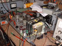
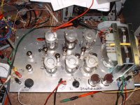
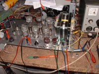
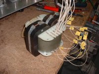
I recently made a breadbord Power amp for some examitations, especially with the grid currents. To estabish the facility for an individual idle setup for each valve, it is neccessary to use an separate drive valve for each opt valve.
I use six 12B4 valves which I had between my odds and ends. A widely makeshift power supply deliver the different voltages as there are 12.6V @ 6.5 Amp for the GU50 and 12B4, 6.3V @ 0.6A for the 12AT 7 and the 12 AU7, -160V g1 Voltage, + 250V g2, +400V input/phase split/ driver and +900V plate via variac.
The opt is also homebrew. It is a SE150a split tape core rpp 2,2k / 400W, 35 Hz/-3dB.
Some values in the circuit diagram has slightly changed while working on the amp.
The results of the last test delivers 440W into 4 Ohms ,the plate voltage drops down to 840V. The THD is 6% , 1 kHz
The grids of the op valve driven up to 20V peak. The idle current is set to 35mA. The input for full blast is 500mV. In this setup I feed the grids and screens via lab power supplies, not to see on the piccs.
Some suggestions for improvements and comments & crits are welcome.
73
Wolfgang
Here are some pics of the setup:
Attachments
Last edited:
Nice
Hi Funker.
Compliments: Nice circuit - I like the driver setup - pretty elaborate but I give you it does enables precise setting of each power tube bias in a much better way eliminating the need for selecting the tubes - which I have to.
The symmetical NFB is a nice touch - I probably would have used the sectons for cathode feedback on the power tubes instead. You decrease the effective damping factor by the loss in the OPT core not taking feedback directly from the speaker section but looking at the core size used it is probably negligible anyway.
I recently published a circuit using symmetrical feedback in a mixture of voltage and current feedback taking into account the MFB from the speaker coil itself. Works beautifully with large diameter woofers. Food for thought, maybe?
Hi thebasher,
due to grid current drive , there are a great amount of THD at high output levels. The tight coupled balanced nfb reduce these amount of THD drastically.
At my first considerations I would leave the output floated. But now my decision is to establish a second nfb from the speaker terminals to kathode of the input valve.
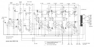
Another change is alredy done , I inserted a adiddional stage with a 6CG7between the 12AU7 and the six 12B4. The the gain of the 12AU7 is lowered by increasing the both kath. and plate resistors . The additional stage extend the maximum output swing from 50Vrms to amazing 80V rmas. So now my driver circuit got enough headroom without the risk to be overdriven before the output stage reach its maximum power.
The driver supply is now 500V. My experiences are still ongoing . My last test bringing 450W with 4% THD. The frequency range is from 30-15000Hz at Full power and 20-20000Hz with -3dB at the bandlimits. The grids are positve driven up to +20V peak.
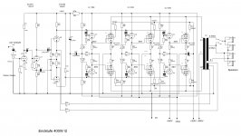
Here are the latest schematic.
73
Wolfgang
DF6ZC
Edit.
There is no way to put a better schematic quality into this post. I tried pdf but the programm say to much data. The original schematic is drawn with S-plan!
Attachments
Last edited:
Voltage + Current NFB
Hi Funker.
Here is the circuit I was talking about. It is basically a balanced/symmetrical amplifier from in- to output, not unlike your circuit.
What is interesting here is the 0.47 ohms resistor(R25) in series with the OPT secondary. You will probably say, that I am deteriorating the damping factor and to a certain extent it is true - but what I am really accomplishing here is producing a signal, which reflects the current of the counter EMF from the movement of the speaker coil - in other words: Motional feedback compensating for the erratic overshoots of the woofer cone.
Philips applied the principle in the late 1960's in a small two-way speaker with two built-in power amps and electronic cross-over. The woofer was a special design with two voice coils where the second voice coil provided the feedback signal.
The principle was called MFB or Motional Feed Back but never succeeded commercially since the units were quite expensive. They sounded very, very good for their size. I had a pair I regretfully departed with.
I have adapted the principle here using standard speakers and components, but dual voice coil woofers are available and might be considered as a more effective way of obtaining a true feedback signal - but it will be a voltage feedback and not current.
You may want to experiment a bit with the value of R25. The WW pot R24 can to a certain extent be adjusted to maintain the proper AC balance in the differential input stage.
I really built this because today's woofers simply do not have the huge magnets and efficiency of speakers of the 50's and 60's and are thus susceptible to cone overshoot due to the relatively poor damping factor of tube amps.
Does it work? Oh yes. This particular design is used as a playback reference amplifier in my modest recording studio driving two Tannoy 15" 385 coaxial (or as they called them 'dual concentric') speakers. The output power is about 24W/channel - more than adequate for the Tannoys. I have some recordings made with two Neumann KM84's and a Nagra IVS reel-to-reel tape recorder and it sounds incredibly clean and natural (chamber music and choir). Digital recorders - eat your heart out.
The harmonic distortion is measured to be less than 0.1% at 20W at the power bandwidth at 40-15,000 Hz into an 8 ohms non-inductive load resistor. The 3rd harmonic is too low to register on my test gear.
However, if I use a speaker as a load the apparent distortion goes haywire according to the analyzer because of the current feedback signal:
The NFB current feedback is regarded by the analyzer as 3rd harmonic which it is not.
But subjectively it sounds good - very tight bass which was the whole point and clear high frequency reproduction totally without audible intermodulation as opposed to standard tube amps driving complex multi-unit speakers with crossovers and other complex loads.
The circuit will work with virtually any output tube. I have used it with 6BQ5/EL84, 6L6GC, EL34 and KT88. ?lenty of drive for any tube.
Attachments
Hi Funker,
can you give dimensions of your C-cores and how much the iron weighs? thanks....
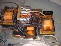
Hi Tony,
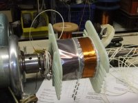
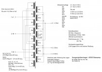
The Transformer is a DIN standard C core , SE150a , weight is app. 3.3kg
it need app. 2.8 kg copper wire , the finished trafo with the mounting frame weights 6.5kg.
Here are the winding scheme:
73,
Wolfgang
Attachments

Hi Tony,
The Transformer is a DIN standard C core , SE150a , weight is app. 3.3kg
it need app. 2.8 kg copper wire , the finished trafo with the mounting frame weights 6.5kg.
Here are the winding scheme:
73,
Wolfgang
Hi Funker, gold info, thanks....

Ok, Tony, thanks!
We call these sockets Septar on our side of the Atlantic, and yes, they're still available...
Another point: An output power of about 120 watts can also be expected from a pair of 6KG6A/EL519/40KG6A/PL519 tubes, running at about 420 volts and driving a load of about 1400 ohms. A pair of Circlotron monoblocks I've built about ten years ago generates even more: 144 watts right before clipping from two PL519s, running at 480 volts, into a load of 400 ohms (that equals 1600 ohms at a common PP design).
Best regards!
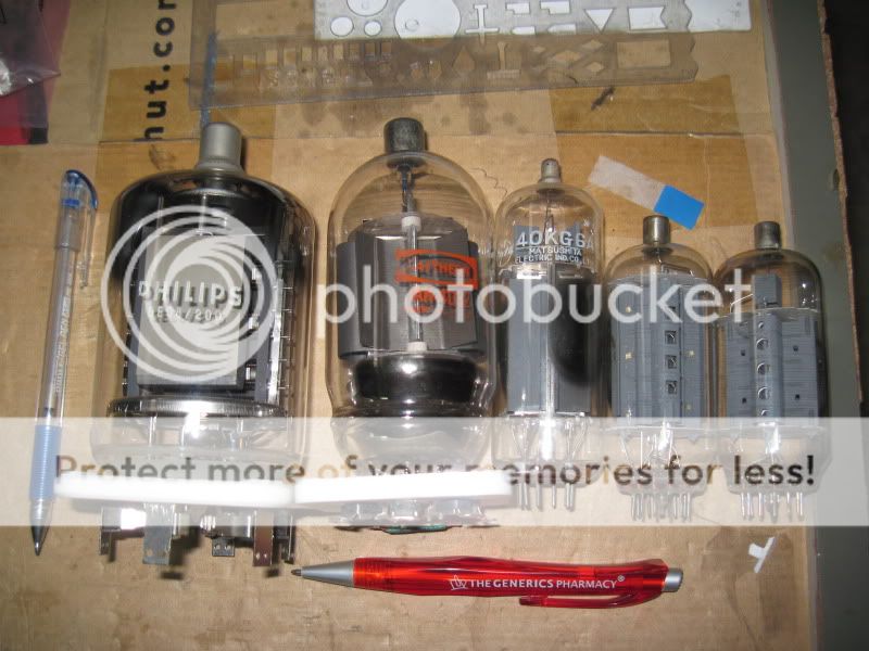
Hi Kay Pirinha,
thanks for the heads up.....to date these are tubes that i have waiting to see action in a pp amp...
from left to right, QE08-200, RK4D32, 40GK6, 6LF6, and 6HF5.....
Hi Funker.
Here is the circuit I was talking about. It is basically a balanced/symmetrical amplifier from in- to output, not unlike your circuit.
What is interesting here is the 0.47 ohms resistor(R25) in series with the OPT secondary. You will probably say, that I am deteriorating the damping factor and to a certain extent it is true - but what I am really accomplishing here is producing a signal, which reflects the current of the counter EMF from the movement of the speaker coil - in other words: Motional feedback compensating for the erratic overshoots of the woofer cone.
Philips applied the principle in the late 1960's in a small two-way speaker with two built-in power amps and electronic cross-over. The woofer was a special design with two voice coils where the second voice coil provided the feedback signal.
The principle was called MFB or Motional Feed Back but never succeeded commercially since the units were quite expensive. They sounded very, very good for their size. I had a pair I regretfully departed with.
I have adapted the principle here using standard speakers and components, but dual voice coil woofers are available and might be considered as a more effective way of obtaining a true feedback signal - but it will be a voltage feedback and not current.
You may want to experiment a bit with the value of R25. The WW pot R24 can to a certain extent be adjusted to maintain the proper AC balance in the differential input stage.
I really built this because today's woofers simply do not have the huge magnets and efficiency of speakers of the 50's and 60's and are thus susceptible to cone overshoot due to the relatively poor damping factor of tube amps.
Does it work? Oh yes. This particular design is used as a playback reference amplifier in my modest recording studio driving two Tannoy 15" 385 coaxial (or as they called them 'dual concentric') speakers. The output power is about 24W/channel - more than adequate for the Tannoys. I have some recordings made with two Neumann KM84's and a Nagra IVS reel-to-reel tape recorder and it sounds incredibly clean and natural (chamber music and choir). Digital recorders - eat your heart out.
The harmonic distortion is measured to be less than 0.1% at 20W at the power bandwidth at 40-15,000 Hz into an 8 ohms non-inductive load resistor. The 3rd harmonic is too low to register on my test gear.
However, if I use a speaker as a load the apparent distortion goes haywire according to the analyzer because of the current feedback signal:
The NFB current feedback is regarded by the analyzer as 3rd harmonic which it is not.
But subjectively it sounds good - very tight bass which was the whole point and clear high frequency reproduction totally without audible intermodulation as opposed to standard tube amps driving complex multi-unit speakers with crossovers and other complex loads.
The circuit will work with virtually any output tube. I have used it with 6BQ5/EL84, 6L6GC, EL34 and KT88. ?lenty of drive for any tube.
Hi thebasher,
your circuit is high alert
The current NFB is a great idea to compoensate unwanted speaker properties. I know the old Philips NFB self powered speakers. As they are, yes they sound very good, especially for their size.
But on the other hand these combined voltage/ current feedback give its advantage for only one speaker setup which has to be precisely adjusted.
If the amp should work with some differnt kind of speaker it would be the best to obtain a low source impedance of the dedicated amp.
Since the NFB loop now include the speaker, the amp and the speaker are to seen as one unit and the only way to measure their properties with appropriate test equipment is by using a test mike instead feed the output voltage of the amp to the test gear.
In my case, this amp shall be the output stage of a Bass Guitar amp. As I sad a Bass amp , a low THD is not the aim. I want huge Power output as it bring this sort of grunt the rock musicians are really like. The amp is intended to operate with an 8 speaker bass cabinett, maybe fitted with 10" chassis. For instance, it may be possible to place the potmeters for the both voltage and current nfb on the back of the amp. But I cannot believe that an Musician is able to find the proper settings to a certain cabinett.
With certain settings you might damge or even destroy the speaker(s) or the amp. So this kind of controls belongs to the inside of an amp away from curious musicians hands.
I will keep your circut in mind if I would once building self powered monitors with valves .
My current monitors are K+H O98. I use the wavelab sound processing software from Steinberg with an M-Delta 8 Channel sound interface and a RTW Peakmeter.
Thank you for your input
73
Wolfgang
wow, that looks smoooth
hmm, any reason not to split the clear tape before winding the thin wire ?
looks like it crumples a lot
it might not if cut in the middle
but whatever, it looks cool
Hi tinitus,
the thin winding you see is the nfb coil. The next layer is another clear Tape, followed by another thick secondary layer.
Normally I should use a thinner foil, but I didn´t had that. And If I would cut it into two halfs the edges would form a recess an thats aggrivate to bring the wires straight onto the coil former.
73
Wolfgang
Well, I think the amplifier shown in #25 has neither MFB nor negative feedback, given by the shunt resistor R25. Current driven NFB would decrease the output voltage if output current rises, in other words, it would increase the output impedance. This would not be beneficial at all! In fact, we have current driven positive feedback here, in order to decrease output impedance. In the mid-fifties this kind of circuitry was "en vogue" in Germany. The then well-known FUNKSCHAU magazine showed many examples.
By chosing the right feedback factor, we can reduce output impedance dowm to zero - and far beyond! And this is exactly the problem Funker describes above. Output current strongly depends on load impedance, and as we all know, a speaker's impedance is not that constant. So in fact it's almost impossible to adjust this feedback correct - even if only one certain speaker is intended to be used. Thus the lifespan of this circuitry was rather limited - it disappeared as quickly as it arose.
Cheers!
- Status
- This old topic is closed. If you want to reopen this topic, contact a moderator using the "Report Post" button.
- Home
- Live Sound
- Instruments and Amps
- Real bass amps have tubes – semiconductors are musical director trainees