Hi, Is there any reason one could not put the bypass capacitor for the boost/fat switch in the footswitch itself? And similarily, could one put a resistor with it to change the total cathode resistor's value?
I don't want to use a relay switch to do it either.
Thanks...
Daniel
I don't want to use a relay switch to do it either.
Thanks...
Daniel
If I understand you right, you would have footswitch/amp cable with V1, V2 and earth leads? Could use stereo coax cable with 6.5 mm TRS plugs?
And also 3PDT switches and battery to allow indicator LEDs so you know where you are at a glance ie when the bass player trips on your rig") ...
...
have fun
JimG
And also 3PDT switches and battery to allow indicator LEDs so you know where you are at a glance ie when the bass player trips on your rig
...have fun
JimG
If you are switching out the cathode parts completely like that, it is going to pop.
COnsider this approach. If you want to switch between 3k and 1.5k cathode resistors (I am making up the numbers, not using yours at the moment), don't wire a switch to select one OR the other. Wire one 3k permanently, and then just switch another 3k in and out of parallel. That way the resistance still switches from 1.5k to 3k and back, but the cathode circuit is never opened.
Same with the caps. If you want to switch between 0.68uf and 220uf, don;t select between them, just wire the 0.68uf permanetly, then switch the 220uf in and out of parallel. Leaving the 0.68uf in parallel with the 220uf won;t matter. 220uf and 220.68uf won;t sound any different. And when they are closer, say 10uf and 20uf, instead of slecting one or the other, just wire in the smaller one, then switch in another in parallel to add on what you need.
You can do this with any pair of resistances. Wire the higher choice in permanent, then calculate what parallel resistance would result in a total resistance of the desired value for the lower resistance setting.
This results in less stuff switching in and out and less stuff requiring long wires.
I wasn't suggesting you change the numbers you already settled on, just suggesting a different way to get there. Caps are more obvious since you find situations like 0.68uf and 220uf. You can always find a stock value resistor for any situation. If you wind up needing 1768 ohms, 1800 ohms is close enough - a standard value. And when I learned electronics, 5% was as good as resistors got other than in labs. Nowdays 1% resistors are easy to find and not expensive, so if you want some odd values, you can still get darn close.
Pops occur when unterminated points in the circuit are switched in and out - usually a cap with a free end. The trick is to keep the caps charged. SO a simple example: Let's say you want to switch a 22uf cathode bypass cap in and out as a gain boost. Just in/out, so cap or no cap. Every time you close the switch, the cap has to charge to the cathode voltage. It does this in an instant, causing a pop. If you put a high value resistor across the switch, no pop. I use 1meg since I have a bunch, but 470k or 220k would work. When the switch is open, there is the 1meg resistor in series with the cap. That basically makes the cap go away electrically. But it is sufficient to keep the cap charged. And when you close the switch, the cap was already charged, so there is no spike of charging current.
If you look at commercial guitar amps, I think you will find a resistor in that duty wherever caps are switched in and out. Same goes for places like relays switching circuit paths.
I went through the numbers and came up with values that add in parallel to be close to what I'm planning. I started with the highest value resistor like you suggested and chose the rest to match with that. Same with the caps, but in series.
I have heard about the large resistor on switches, just don't fully understand it. I will check out some schematics on it though. Before I thought about this idea, I had two boost switches from two tubes. The only pop I would get would be the first time switching it in, but after that there would be none.
So, in conclusion, if I have one cathode resistor connected and choose others, in parallel, there should be no pop. But with the cap, the 0.68, there would be one initially, but then fine after that.
One last question about the cap voltage rating: Does a lower voltage rating mean less pop? Ex: 68uf@25v vs @100v...
Thanks again,
I personally would use a relay (or maybe even fet switching) ...
I just finnished building a 2 channel hybrid Tube/solid state amp and tried to do the channel switching useing just a DTDP stomp switch useing shilded cable and it was noisy as hell , ended up having to use a couple 5v relays and the noise problem was solved ......
It just really picked up a lot of RF hash having an extra 15+ feet of wire that the signal had to go through which I suspect would be just as bad or worse switching cathode resistors ......
Cheers
There are multiple issues here. There is how to do the component switching in the first place, then there is whether to drag the signal path out into the real world with 15+ feet of cable or leave it all inside and bring relay control lines outside the amp.
A toggle switch or a relay are the same thing electrically, and using one or the other to switch in a cap will result in the same pop if not terminated.
I personally would never pull the signal wiring outside the chassis. I don;t consider relays a burden, I consider them a gift from God. But the OP specified not using them, so I concentrate on the other issue. Relays allow one DC control wire to control as many switch closures as you like. One wire can control as many relays as you want, and they can easily control unrelated points in the circuit from the same control signal.
dscott, the resistor thing is not hard to follow.
Imagine you have a cathode resistor with a volt across it. Pretty common. Now connect a cap to the cathode. Right now the cap is uncharged, because the other end is not connected to anything. Now the moment I ground the free end (which is what happens when I switch the cap in), that cap has to charge up to 1 volt DC. There is a brief current surge through it. Not enough current to harm anything, but enough to cause a voltage glitch on the cathode. And that makes an audible signal we hear as a pop.
Now what if we wire a 1 meg resistor from that free end of the cap to ground. The cap is now permanently in the circuit, but the 1 meg series resistance prevents it from having much effect. However, the 1 meg completes a path for the cap to charge. This happens an instant after power-up, takes maybe a millisecond. Once the cap is charged, there is no current through it, and thus no current through the 1 meg either. No current means no voltage drop, Ohm's Law. No voltage drop across the 1 meg means the entire 1 volt is across the cap - it's charged.
Now if I short across the 1 meg with a stomp switch or a relay, the cap is now fully in the circuit, and the cap didn;t have to charge, it was already charged. There is now and always was 1 volt across it. No voltage change means no current spike, which means no pop.
Thanks Enzo, that really helps. So, the 1M connected to the center lug of the switch and the other end to one of the other lugs connecting the RC circuit to ground. The 1M keeps the cap charged but doesn't allow enough current to flow out as it does when it is 'shorted' by the switch. I think I 'see' it now.
About the line from the amp... In the previous footswitch I had the cap in the chassis and the ground connection through switch. The stock cable did not have any shielding and I didn't notice any noise either. Is that expected? I would assume so since the unit was a generic replacement and would have come w/ shielded cable if it was necessary.
Thank you all...
Case closed...
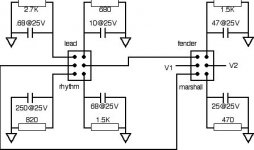
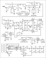
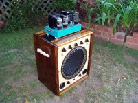
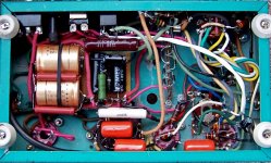
Hi all, In case you're interested here is a pic & schematic of what I made. The footswitch works really well. I've yet to add the popping resistors and led, tomorrow, but the amp sounds great. From good clean, enough for acoustic guitar thru a PA speaker, to amazing distortion. The "Fender/Marshall" switch makes a world of difference in the sound and the rhythm/lead switch is more like a high/mid boost. I really like it. I'll be setting it up at a studio this week w/a 212 cab and a room I can crank it for more than 15 seconds-landlord stinkeye.
Thanks for all the input here and other threads. Especially to you Enzo, you've helped me before and I've read many other threads you've responded to that are always explained simply and helpfully. I love this forum...
Attachments
- Status
- This old topic is closed. If you want to reopen this topic, contact a moderator using the "Report Post" button.
- Home
- Live Sound
- Instruments and Amps
- fat/boost switch