jfets are supposed to be the masters of hi-Z input
how high input impedance can we achieve using tube only ?
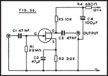
The control grid of a triode tube has very high impenence. It's basically an open circuit. But you can't use it that way. You must provide a path from grid to ground and the minimum size grid leak" resister will be found in the tube data sheet. For most preamp tubes I thinkit's about 2M but "everyone uses a 1M grid leak resistor and most of these get soldered to the input jack. The input impedance is the same as this resistor.
But ask yourself, do you really want more than 1M? Why? I think you will get even more noise pickup from the environment
ChrisA;2718397 But ask yourself said:yeah
I now also think anything above 100K ought to work
yeah
I now also think anything above 100K ought to work
No, you really don't want to plug your guitar into an amp with 100K input impedance. the pots in the guitar across the cable are 250K They are in effect in parallel with the amp and you know has parallel resistors add. The amp needs to be high relative to the tone pot.
You must provide a path from grid to ground and the minimum size grid leak" resister will be found in the tube data sheet.
ahh, I often go back and read again, in case I missed something

looking at ecc81
it says 1M limiting value
I suppose this means 1M is max recommended value 'grid leak resistor'
but if thats also the resulting imput impedance, it would be just fine
so far so good
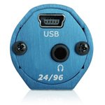
this 'thing' has instrument hi-Z input, and connects directly to USB port
even has headphone out
not really cheap, but what else do you need
plug it into your home stereo media streamer
or via PC with all kinds of software
and thats it
very tempting
even has headphone out
not really cheap, but what else do you need
plug it into your home stereo media streamer
or via PC with all kinds of software
and thats it
very tempting
Attachments
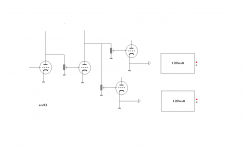
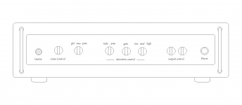
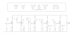
hey, I chopped this out of a probably nice amp
but I wonder, running this at just above 100V+, maybe it would make a nice buffered distortion preamp
only part of it ofcourse
btw, I night have found my preferred bass sound
adding just a little touch of natural growl, and its almost similar to the gnarly sound of a real acoustic double bass
which I happen to like a lot
Attachments
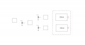
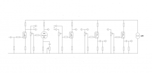
also, this might be cool
both gain and frequency adjustable
still need output buffer to drive a solid state amp
either the same mosfet
or I have some 6C19n that ought to run fine on this 'lowered' voltage
well, easier said than done
hey, maybe the 6C19n would make nice distortion with even lower voltage

hmm, I would need two input options, with a switch
one with all mosfets, and one with tube coupled in
but thats the least of my problems
is this completely nuts
both gain and frequency adjustable
still need output buffer to drive a solid state amp
either the same mosfet
or I have some 6C19n that ought to run fine on this 'lowered' voltage
well, easier said than done
hey, maybe the 6C19n would make nice distortion with even lower voltage
hmm, I would need two input options, with a switch
one with all mosfets, and one with tube coupled in
but thats the least of my problems
is this completely nuts
Attachments

Attachments
The answer to getting hi input Z at AC whilst maintaining that lower max Rg1 value for the input tube was in an earlier post (D96 was it?). Divide the cathode bias resitor, bypass the top resistor and connect the RG1 to the junction of the 2 resistors instead of 0V.
That is BOOTSTRAP the Rg1. DC wise you still meet the max Rg1 requiremnt (and it is at DC where it is important) but you also increase the effective AC impedance.
Cheers,
Ian
That is BOOTSTRAP the Rg1. DC wise you still meet the max Rg1 requiremnt (and it is at DC where it is important) but you also increase the effective AC impedance.
Cheers,
Ian
The answer to getting hi input Z at AC whilst maintaining that lower max Rg1 value for the input tube..........
maybe I understand what you are saying, but only slowly
it bothered me that the 6C19n might not be suited fore Hi-Z input
btw, I removed one att
I think D96 said that I could use the cathode bias like a gain control
but now I want to use as distortion gain control
not yet sure how much gain I will have, or how much I need
I got a nice DIY stereo power amp yesterday
built it a long time ago, and now got it back
will try a few experiments
Attachments
Divide the cathode bias resitor, bypass the top resistor and connect the RG1 to the junction of the 2 resistors instead of 0V.
That is BOOTSTRAP the Rg1. DC wise you still meet the max Rg1 requiremnt (and it is at DC where it is important) but you also increase the effective AC impedance.
Cheers,
Ian
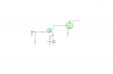
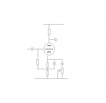
something like this
I remembered now that max grid resistance of 6C19n would be 500K
but should be no problem to have a jfet in front of it
apart from the 'problem' with different voltage
I was trying to avoid that by using a mosfet instead(2sk2013)
at least I suppose it would be ok with this higher voltage
btw, I plan to have a switch with 3 different cap size fore the cathode/gain control, and pot adjust will be on front, or as rotary switch with fixed resistors
if possible at all
Attachments
Yes,
Something exactly like that.
The signal voltage at the cathode follows the signal voltage on the grid. For AC signals the signal across Rg1 is therefore about 1/10th what it would be if the Rg1 were tied to 0V instead - for AC signals therefore Rg1 looks to be about 10 times as large. So if you use a 500K resistor for Rg1 it will look like about 5 Meg Ohms as far as its AC input impedance goes.
Of-course there is nothing wrong with the proposed JFet buffer either - the boostrap arrangement might just be a little easier (less parts).
Cheers,
Ian
Cheers,
Ian
- Status
- This old topic is closed. If you want to reopen this topic, contact a moderator using the "Report Post" button.
- Home
- Live Sound
- Instruments and Amps
- Switchable Hi-Z input impedance, how ?