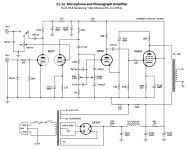
I have this little Masco ME-8 amplifier whose circuitry has been universally condemned by the local braintrust, and yesterday I happened to stumble across this schematic in my RCA tube manual, which uses virtually identical chassis hardware, making a retrofit pretty much a no-brainer if this circuit is worthwhile. It certainly seems normal/acceptable to me for use as a guitar amp (ie. linearity, distortion and bandwidth are not really a concern.)
But the ME-8 used octal tubes and this RCA design uses 9-pin tubes, but I believe I can use a 6SL7 in place of the 6EU7, and find a suitable octal version of the 1/2 6SL7 for the other tube. Or perhaps I could incorporate another triode into the circuit somehow, in order to end up just using two 6SL7s.
Can I just parallel the 2 triodes and adjust the operating points accordingly?What does that accomplish? More current flow certainly, but more gain too? Or might there be a better way to incorporate another triode without adding too much complexity (the chassis is really small/tight).
Your thoughts?
..Todd
Attachments
I had a look at your other thread on the Masco. Why don't you just use the Masco as is for a guitar amp? A lot of classic guitar amps had grid lead bias just as the Masco does on the Mic input. If the problem is that you are using stompboxes and the Mic input is saturating from the higher input, then just convert that 1st stage into cathode bias.
I'd change the first stage (In1) from grid-leak bias to cathode bias with a bypass cap. Remove the 100pf cap and move the series resistor to the grid as a gridstop. And change the tone controls to a more traditional tonestack. THree stages is plenty, but you could make the second bottle a dual triode and either parallel them as you suggest or add an additional gain stage for more overdrive (but you might want to add an additional gain control between stages to give you control over it).
Hi TheGimp,
I think adding an additional gain stage would add too many parts for the chassis size -- especially the added pot needed to control it. I don't want to add a pot.
What would you consider a more traditional/suitable tone stack? It would still have to be a passive R/C network though or it probably won't fit (physically). I haven't played guitar in many years so I'm not up on guitar circuitry. (And I'm not exactly a whiz with hi-fi circuitry either.)
..Todd
Compare the schematic of the original Masco with the Fender Champ 5C1. Looks like a no brainer to me. I would fix it and try it first it might just rock! If not rewire it into a Champ using the 6SJ7, 6L6GCF and 5Y3.
If you want a tone control the extra tube can supply the gain needed to make up for a tone stack loss. I would stick to a FMV (Fender Marshall Vox) tone stack since it is optimized for guitar use. A Baxandall tone control is excellent for HiFi but it is rarely used in guitar amps since it is optimized for action outside the guitars fundamental frequency range.
I have seen a few guitar amp schematics that use a pentode first stage followed by the tone stack then a triode then the SE output tube, but I can't find one now.
Champ 5C1:
http://www.drtube.com/schematics/fender/champ-5c1-schem.gif
I'll try it as-is first.
The local feedback resistor (R13) takes away gain and distortion. It would probably sound better without it.
The local feedback resistor (R13) takes away gain and distortion. It would probably sound better without it.
Good point. thanks.
Grid leak bias is preferred for a harp amp, try it! But it won't work well with a high-level input like a pedal. The Fender tone stack is NOT flat - it has a notch in the low midrange that makes a guitar sound MUCH better. A Baxendall can be made with the proper roll-of frequencies for guitar, but won't sound good when set "flat".
Hi Tom,
") I couldn't blow a major scale on a blues harp -- and that doesn't really bother me. I'll stick to guitar (until someone takes it away from me at least).
I couldn't blow a major scale on a blues harp -- and that doesn't really bother me. I'll stick to guitar (until someone takes it away from me at least).
I understand what you're saying about the tone stack. I'll worry about the basic operating point stuff first though, and add a tone stack after things are working fine.
..Todd
I couldn't blow a major scale on a blues harp -- and that doesn't really bother me. I'll stick to guitar (until someone takes it away from me at least).I understand what you're saying about the tone stack. I'll worry about the basic operating point stuff first though, and add a tone stack after things are working fine.
..Todd
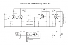
Okay, I've done a little research about tone stacks. I'm not sure where the best place to add one to a champ circuit would be though. The Masco circuit has an additional gain stage, which I consider worthwhile adopting, so I wonder if it makes sense to add the tone stack between the 1st gain stage and the pentode. And I understand that it's a good idea to use a cathode follower before the tone stack to provide a better impedance match for the filter network (which turns out to be handy for consuming the 2nd triode in a twin tube).
So here's my resulting schematic. Would this topology work? If so, I'll get out the data sheets and calculator and start figuring out values.
I was listening to some old 5C1 champs on Youtube. Very cool sound. I might build this as a separate project just because.
..Todd
So here's my resulting schematic. Would this topology work? If so, I'll get out the data sheets and calculator and start figuring out values.
I was listening to some old 5C1 champs on Youtube. Very cool sound. I might build this as a separate project just because.
..Todd
Attachments
Last edited:
Oh, one more guitar amp question. The Masco uses a choke in the power supply and the Champ just uses a resistor. Do chokes do something detrimental to guitar sound, or should I go ahead and add one to the modified champ schematic? I assume it was done on the Champ just because resistors are a heck of a lot cheaper than chokes. But some of the cost-cutting efforts had a beneficial outcome in terms of guitar amp sound. That's the essence of what I'm curious about here.
..Todd
..Todd
Getting the distortion right isn't easy, believe me. So, even if you may get lucky at your first try, I really doubt it. If I were you I will copy this design:
Bobs tube type guitar amp page
* 6SL7 is a fine sub for the 12AX7.
Bobs tube type guitar amp page
* 6SL7 is a fine sub for the 12AX7.
Last edited:
Getting the distortion right isn't easy, believe me. So, even if you may get lucky at your first try, I really doubt it. If I were you I will copy this design:
Bobs tube type guitar amp page
* 6SL7 is a fine sub for the 12AX7.
Hey, great link! Good information. It sounds like this guy has done all the research into this exact issue (and he's done all the calculating already which is another bonus.) Thanks Cassiel!
..Todd
Getting the distortion right isn't easy, believe me.
Making a clean amp is the easy part. Making one that cranks isn't. That circuit is a good place to start if you have decided to rip it up and start all over.
I have built several amps using a circuit very similar to the "Mabel" shown on that web page. In fact the gain stages used in the circuit I just posted in the $100 amp challenge thread are identical except that I used a mosfet for the follower instead of half a 12AX7. The 6SL7 has slightly lower gain than the 12AX7 but would probably be fine for most music.
Making a clean amp is the easy part. Making one that cranks isn't. That circuit is a good place to start if you have decided to rip it up and start all over.
Yup, no doubt. And there's a million ways of "cranking" that may or may not be to anyone's particular liking. Guitar amps are like houses or cars; everyone has their own idea what ideal means to them.
I doubt I'll rip up the Masco and start over, but I liked the sound of those Champs I listened to on YouTube so much that I have an itch to build one (but with extra crank and some added tone controls), so I'm thinking more of a scratch build.
..Todd
In most guitar amplifiers the volume control goes after the first stage, because guitars have volume control on themselves.
So a better idea is to have volume control and tone stack between the first two stages, and add a master volume after the second stage. Standard way.
So a better idea is to have volume control and tone stack between the first two stages, and add a master volume after the second stage. Standard way.
Yeah, it's amazing the learning curve and the information tangent this little Masco amplifier has sent me on. Learning tons about guitar amps since I've approached tube amps from this angle. It's been a fascinating week and I don't expect that to let up any time soon.
I wish I could go back in time to the years when I was surrounded by guitar amps but never gave their internals much thought. Now, I'd be measuring and diagramming them all. Back in my music years, guitar players just knew which amp-sound they liked, based on what they played with at the local music store. Now, guitar players know practically everything that goes on inside the amp -- at least as far as modding, and which mods or topologies they like, and why. I suspect the internet has brought about virtually all of this change.
..Todd
I was just puttering with this little Masco amp today to revive it in its current state. I've replaced the enormous filter caps that someone added to it at some point in its career, with ones much closer to the original sizes spec'ed.
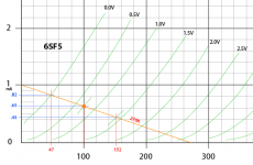
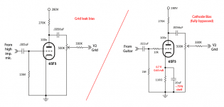
Then I noticed the grid leak resistor on the input stage had at some point vaporized. The input tube, a 6SF5, was grid leak biased and I don't have a 15M resistor to replace the old with, so I decided to convert it to cathode bias. I planned to do that anyway one day, this just sped up the process. The goal is to change only the components necessary to convert the bias scheme and leave the rest as is.
For today's dumb question, I just want the diyAudio brain-trust to see if I'm doing this conversion correctly. I grabbed the 6SF5 datasheet curves and plotted the existing load line and voltage points to determine what a reasonable bias point would be, and it looks to me like 0.7v/0.65mA will work.
Here's the circuit changes and load line I used. am I on the right track?
..todd
Attachments
Last edited:
- Status
- This old topic is closed. If you want to reopen this topic, contact a moderator using the "Report Post" button.
- Home
- Live Sound
- Instruments and Amps
- Retrofit idea, need advice, 6L6SE guitar amp