6AF11 amp
Neat, compact, cool")
Cheers, JimG
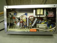
Here are the guts of the little 6AF11 amp.
Neat, compact, cool
Cheers, JimG
Here are the guts of the little 6AF11 amp.
Very compact!
Nice job...
I used a compactron in an amp once and found it would be on the verge of squealing at full gain.....It took a quite a few iterations to eliminate the squealing oscillation but I finally got it out of there.
I have waffled back and forth on the compactron amp idea. I started one on perf board with sky wired parts and clip leads. It was a good multi frequency radio and TV jammer so thats where it stopped. I may revisit it if there is time but it doesn't look good. There are 3 pin comaptible tubes that fit. The 6AF11, the 6AS11, and the 6BD11. They are all in good supply and two are on the dollar menu.
My design uses two tubes. The high Mu triodes are the preamp stages the medium Mu triodes are the PI and the pentodes are P-P output. I get about 10 watts out of it cranked. No distortion numbers or clean power readings were taken since I never tamed it. I started a PC board layout but came to realize that trying to use two tubes with the signal going back and forth between them isn't a good idea. The layout could not be optimized.
Made PC boards for two new experiments last night. One is a 4 tube version of Amp 1.0 and the other is just a preamp with 2 tubes and a "distortion maximizer" circuit. Haven't had time to cut and drill them yet.
Personally I hate doing ship-in-a-bottle builds. But whenever I have lots of space I get ideas of adding features and the space just disappears. That being said, I see room enough in their for a reverb loop (hint, hint). Just kidding.
I really like it for the compact size but it was difficult to wire. I had the circuit jumper-clipped together on the bench and had it working, but low and behold when I mounted everything in the chassis, there was that pesky oscillation again. Stupid wiring mistake on my part.
Reverb loop? In there? HA! Luckily I have have an external digital reverb.
I really like it for the compact size
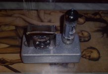
Then you gotta love this one. I have a soft spot for small and cute things but....damn, I'm beginning to think I bought too small a chassis. LOL. That OPT (believe it or not) was the partner of an ECL86 output tube (vintage reel to reel tape recorder).
Attachments
Then you gotta love this one. I have a soft spot for small and cute things but....damn, I'm beginning to think I bought too small a chassis. LOL. That OPT (believe it or not) was the partner of an ECL86 output tube (vintage reel to reel tape recorder).
That's what she said
j/kIs that a pedal box? I think I have a couple about that size setting here. I always planned on doing one of those 6021 sub-micro amps but never got around to it.
Yeah, that's for a pedal box.
Yeah, that's what she said. So I built this as a gift for our first year anniversary.
That's what she said
Yeah, that's what she said. So I built this as a gift for our first year anniversary.
Attachments
I don't check this site often, so I'm a little late to this topic - designing an amp to be built on the cheap has been a goal of mine for a little while now.
Ah, the 6AF11... what a heartbreaker. I have come to the conclusion that the 6AF11 and it's ilk are not suited for beginner-to-intermediate builders, especially in high-gain territory. The issue is that triode 2 and the pentode are in close physical quarters, which can lead to feedback issues from plate-to-plate capacitances. Ok, so run them so that the plates are out of phase, right? That might work, except that the pinout puts the grid of triode 2 right next to the plate of the pentode. So your wiring must be immaculate to prevent all possible positive feedback between those two tube sections. An experienced designer could probably create a PCB that minimizes the pinout problem, along with a judicious use of grid stoppers and HF rolloff. Crazy wiring to an external board with slightly too long wires just doesn't cut it...
Right now I'm working on an amp that fits the rules, with the caveat that the output transformer I have (I bought it about a year ago) seemingly isn't for sale anymore... it's a 100V line transformer that was sold by Newark (and presumably Farnell in the UK), model P634T. It was interesting to me because it has an effective impedance ratio of 16k:8,16 ohms, which is a nice ratio for many small pentodes. The one I have is working perfectly in my testbed amp. Anyone know where one can get something similar?
Ah, the 6AF11... what a heartbreaker. I have come to the conclusion that the 6AF11 and it's ilk are not suited for beginner-to-intermediate builders, especially in high-gain territory. .... So your wiring must be immaculate to prevent all possible positive feedback between those two tube sections.
What I get from your post is that you don't believe the amp I built works.
It actually works well and sounds great, from low to full on, with no oscillation as long as the correct biasing and other values are correctly chosen. The wiring is not critical and does not have to be immaculate as you can tell by the closely packed wiring in the photo I posted earlier. I'm also using AC filament voltage. No noise or hum. Like I mentioned before, the circuit I built runs in triode/pentode and with or without negative feedback.
Scott
Last edited:
What I get from your post is that you don't believe the amp I built works...
Not at all! My comments were based on my actual experiences with trying to use this tube in an amp (push-pull, 2W output) with a Fender-style construction (turret-style board with wires leading to the tube pins). I did this because I wanted the amp to be easy to construct, and figured this was the most accessible way to do so. I found that with the tubes I have (actually the 15V heater version - perhaps that makes a difference? perhaps we have different makes of tubes?) the amp was not only quite sensitive to lead dress, but even when not oscillating outright would break into oscillation on signal peaks.
Now, I may have overstated the difficulty in using the tube (this was a high gain amp, and my building methods were fairly crude), but I did sink many an evening into trying to get it to work, so I thought a bit of a cautionary tale might be in order. I guess I should have taken more care in the telling.
And I do believe you that your amp sounds great (the reason I put as much time into mine as I did was that it sounded fantastic while it wasn't oscillating!)
I am using the Parts Express #300-040 transformer. It is a 70 volt to 4 or 8 ohm transformer. It has a bunch of taps and I found a set that works OK for small (2 to 5 watt) P-P amps. It is under $5 too!
Thanks! It looks like it should work out - I can even put an 8 ohm speaker on the 4 ohm tap for the same impedance ratio as the one I have now (which is a 100V line transformer).
(actually, I found that Newark will sell you a P634T - but it comes from Farnell "direct ship" with a $20 surcharge, and they don't even have any in stock! Scrap that one, I guess..)
I'm starting to feel like a yo-yo. Just when I think I may be ready to start heating up some solder again here comes this line.
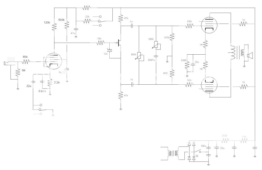
Not to say my latest iteration could not be built by intermediate builders, but the point was to have a easy to build practice amp. So using the delete button I got down to this with the inclusion of a Mosfet (is it OK to use as a phase splitter?). Never tried this before so I do not know if it is functionable. Just figure it is a source follower with an extra resistor.
not suited for beginner-to-intermediate builders
Not to say my latest iteration could not be built by intermediate builders, but the point was to have a easy to build practice amp. So using the delete button I got down to this with the inclusion of a Mosfet (is it OK to use as a phase splitter?). Never tried this before so I do not know if it is functionable. Just figure it is a source follower with an extra resistor.
Printer2, please don't let me curb your enthusiasm! If you have the tubes, give it a shot. One thing that may have had an effect in my amp was that there was not a large amount of physical distance between the two tubes (and that couldn't be remedied without essentially rebuilding the whole thing). Be sure to give your tubes space, and keep your wires short (yes, one of those engineering tradeoffs!)
Ok, cards on the table time. Here's the schematic of my most recent prototype of a cheap amp, minus power supply. As of now it sounds great through a vintage Jensen C8R (one of my few decent speakers, but probably cheating within the design parameters!) Quite conventional with the exception of the phase splitter, which is a paraphase self-split variety, not common but not original either (I did think I came up with it a couple of years ago, but I found it later on the internet in someone else's design! Quit prestealing my ideas, world!)
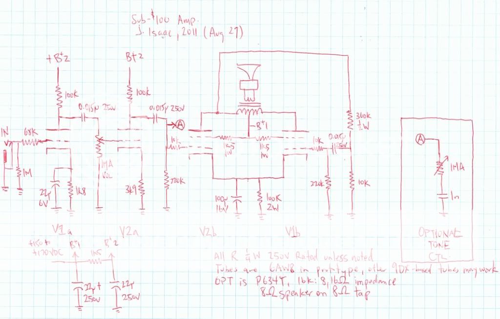
Ok, cards on the table time. Here's the schematic of my most recent prototype of a cheap amp, minus power supply. As of now it sounds great through a vintage Jensen C8R (one of my few decent speakers, but probably cheating within the design parameters!) Quite conventional with the exception of the phase splitter, which is a paraphase self-split variety, not common but not original either (I did think I came up with it a couple of years ago, but I found it later on the internet in someone else's design! Quit prestealing my ideas, world!)
(I did think I came up with it a couple of years ago, but I found it later on the internet in someone else's design! Quit prestealing my ideas, world!)
I have thought I discovered some new tube circuit only to have someone send me a copy of my nifty idea printed in a very old book. I thought I had invented a really cool cathode follower idea until I heard from the holder of the original patent issued in 1957!
I have used this PI / output circuit too, in fact it is in one of my AMP1.0 designs. I have found that it will oscillate if you use a small cathode bypass cap (10 to 25 uF) like typically found in guitar amps AND a crummy OPT (like the Parts Express unit) that has a low frequency roll off and associated phase shift. I didn't come up with that idea either, I found it in a schematic on the web.
I have been told that all possible tube circuits have already been done. I was beginning to believe that until I built a class H design with the plate supply varrying in real time controlled by a DSP. They didn't have DSP's in the vacuum tube glory days.
Curb my enthusiasm? It is good to see that others have gone down the same roads with mixed results. It makes it interesting. It is having to strip my kitchen floor that curbs my enthusiasm.Printer2, please don't let me curb your enthusiasm! If you have the tubes, give it a shot. One thing that may have had an effect in my amp was that there was not a large amount of physical distance between the two tubes (and that couldn't be remedied without essentially rebuilding the whole thing). Be sure to give your tubes space, and keep your wires short (yes, one of those engineering tradeoffs!)
Ok, cards on the table time. Here's the schematic of my most recent prototype of a cheap amp, minus power supply. As of now it sounds great through a vintage Jensen C8R (one of my few decent speakers, but probably cheating within the design parameters!) Quite conventional with the exception of the phase splitter, which is a paraphase self-split variety, not common but not original either (I did think I came up with it a couple of years ago, but I found it later on the internet in someone else's design! Quit prestealing my ideas, world!)
- Home
- Live Sound
- Instruments and Amps
- The Hundred-Buck Amp Challenge