Oops it was late, was not paying attention to the numbers too much, you are right about the tone stack. The first 0.022uF I had in place in another design which could switch the tone stack before and after the first triode. I left it in as it allows the option to do it with this board. I never considered the 1Meg though.Is the first .022uF off the first plate there to allow you to use lower voltage caps in the tone stack? It is not needed if all the caps meet the voltage spec, otherwise yes one HV cap there with say a 1 Meg bleed to gound would allow lower voltage caps in the tone stack. Also, the .022uF is in effect in series with the .1 uF and .47 uF in the tone stack at mid and low frequencies and it will dominate the reactance being of much smaller value. Fender often used .022 or .047 uF in the tone stack, did you really intend to use those big values?
Thanks for the replies,
Yeah I see what you mean about the tube circuits & how they have more than likely been built before.
I also am using new transformers for the PS & OPT, I have my circuit almost complete & will test it out later today, it's looking not to bad at the moment with a lot of even harmonic content.
I'm attemting to stay clear of high amplitude odd harmonics as I really don't like ear piercing shrill sounding amps.
Can't wait to try it out.
Cheers
1st attempt
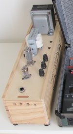
6AK5, 6CL6, 38volt tfmr thro flash cap voltage sextupler, wine box (empty now), output tfmr (7500:8) blew the budget. Will have to try the fender 6G15source (thanks Chris A).
Sounds:
Volume - clean from 8 o'clock to 12 o'clock.
grid current clipping from 12 to 3 o'clock
grid current and cut off limiting from 3 -4 o'clock
Tone - good enough not to bother with tone stack
Loudness - bedroom level if nobody else at home")
Now for 2nd attempt.
Cheers
JimG
6AK5, 6CL6, 38volt tfmr thro flash cap voltage sextupler, wine box (empty now), output tfmr (7500:8) blew the budget. Will have to try the fender 6G15source (thanks Chris A).
Sounds:
Volume - clean from 8 o'clock to 12 o'clock.
grid current clipping from 12 to 3 o'clock
grid current and cut off limiting from 3 -4 o'clock
Tone - good enough not to bother with tone stack
Loudness - bedroom level if nobody else at home
Now for 2nd attempt.
Cheers
JimG
Attachments
Cool name, "Taste of Gippsland"
An externally hosted image should be here but it was not working when we last tested it.
I'm back to fighting oscillations again.
It looks like it might be feeding back through the power supply.
If you wired ground as drawn on your picture it have to oscillate.
Tone - good enough not to bother with tone stack
Best tone control.
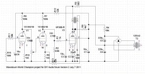
Cool chassis too.Here is corrected schematic, how it is now.
Can you please explain the power supply and output stage, it it too strange looking for my feeble mind... Pretty please?
Sounds on different levels of gain. Almost the same loudness, different timbres. Is it good, or too much compression?
YouTube - World Champion guitar amp project -- sounds on different levels of gain
YouTube - World Champion guitar amp project -- sounds on different levels of gain
Can you please explain the power supply and output stage, it it too strange looking for my feeble mind... Pretty please?
Preamp and screen grid are powered from a network that supplies more of voltage on low signals, less voltage on high signals. It increases tone dynamics decreasing SPL dynamic.
If you wired ground as drawn on your picture it have to oscillate.
Which wiring? First and second stage B+? They actually have an RC stage between them.
Ground is star connection with common point where B+ enters from HP supply.
Which wiring? First and second stage B+? They actually have an RC stage between them.
Ground is star connection with common point where B+ enters from HP supply.
What about input and output jacks?
Input jack is grounded at the capacitor bank where power comes in.
Output tied to star as well.
All of signal path is single end grounded RG-174/U shielded cable.
Are they both isolated from chassis, or form a loop through it?
By the way, I recorded sound on high pitch strings, to show compression of my amp:
http://www.youtube.com/watch?v=pRF05L9btYM
No chassis. This is on a tube-lab type breadboard.
Since there is no global feedback, I've tried removing the ground to the output and letting it float. No change in the oscillation.
I also considered the possibility of feedback between the triode and pentode in the 6GH8A which were stages 1 and 3 which were in phase, so I changed the position of the triodes so that it is 6GH8A Pentode input driving tonestack, 6GH8A Triode second gain stage after tonestack, 6F4P triode 3rd gain stage, other 6F4P triode as Concertina, then the two output 6F4P Pentodes.
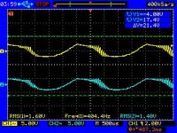
The oscillation breaks out at the peak of the signal and is only seen now on the 3rd gain stage through output.
I switched to a 400Hz test tone.
Since there is no global feedback, I've tried removing the ground to the output and letting it float. No change in the oscillation.
I also considered the possibility of feedback between the triode and pentode in the 6GH8A which were stages 1 and 3 which were in phase, so I changed the position of the triodes so that it is 6GH8A Pentode input driving tonestack, 6GH8A Triode second gain stage after tonestack, 6F4P triode 3rd gain stage, other 6F4P triode as Concertina, then the two output 6F4P Pentodes.
The oscillation breaks out at the peak of the signal and is only seen now on the 3rd gain stage through output.
I switched to a 400Hz test tone.
Attachments
- Home
- Live Sound
- Instruments and Amps
- The Hundred-Buck Amp Challenge