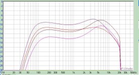
I keep my upper frequency -3dB limit below 10KHz for my guitar amps.
I suggest reducing you coupling cap values.
Coupling caps alter the low end and I suggest increasing them to reach the lowest note on a standard tuned 6 string of the low 80s or the low 40s if the plan is for a bass amp. Drop tunings are popular with lead guitar so 60 Hz might be a good compromise. I've simulated several popular guitar amps and most have a LF rolloff at ten Hz that compares to his 100 Hz referring to the curve in post #480.
HF rolloff is usually accomplished in guitar amps with the 68K grid stopper at the input jack forming a LP filter with the first tube's Miller capacitance. All the grid stoppers contribute to the HF rolloff.
It will be interesting to see how people approach the distortion aspect.
I've got mine to the point where one can dial the power from below 0.1W up to 3W with the distortion staying at about the same level, although the noise floor comes up with power.
First is distortion mode at 0.1W, second is same at 3W before clipping and the third is in clean mode at 1W.
What does it SOUND like? Not many people could figure out the sound from your graph. I think it measures the wrong thing
It is hard to be objective when describing sound. So I think it's best to make objective comments about what can and can not be heard. Examples might be
1) "It cleans up to sound like a Fender champ." (This sound, I think is do to the tone stack even if on a Champ the pots are replaced with fixed resistors but the standard TMB stack is still in there)
2) Distorted power chords sound good but triads and other "normal" chords sound like mud. (this is typical of most "rock" type heavy clipping type distortion.)
3) It's "touch sensitive". Force in the pick controls distortion without effecting loudness so much. (I think amps need to compress the dynamics to make this happen but that's just my theory)
4) the bass strings tend to distort before the others. (or vice versa) Or "tone changes as you move up the neck." I've heard it both ways but I think a lot of people wold go for crystal clear highs and a "crunchy" bass. (It has to do with the freq. response of the first gain stage because it is typically the second gain stage that is driven into distortion.)
5) This amp is design to be a clean tube sound and to by very "pedal friendly".
Those are all objective things one could say or not say. None of them are good or bad, just observations
I don't think the spectra of a 1K signal says anything at all about a guitar amp. 1K is not realistic. try a sweep of the four octave sweep from 80Hz up. That is the range that is used. No point is showing those higher harmonics either as a typical guitar speaker has very little output above about 5KHz
There is absolutely no "correct" answer to how a guitar amp should sound. My preference would be for one to go from "Champ-like" clean to a blues-overdriven sound and use pedals for anything else. In an ultra low power $100 amp I'd also want it to be a combo.
I am going to record some video to show how it works.
Also, I will bring some on BAF in San Francisco. We may need some room for guitar amps, I believe.
Also, I have unfinished bass guitar prototype, but I don't have bass guitar. Anyone?
Bass? Man, mine has been in the case under my bed for at least 7 years now, think I should get new strings?

Since we are on guitar amps,
Does anyone have a copy of the schematics to mod a Gibson GA-5 to the spec as seen in this video?
3:00 minutes in
Viddler.com - Back to the Future Opening Scene - Uploaded by heyuguys
Does anyone have a copy of the schematics to mod a Gibson GA-5 to the spec as seen in this video?
3:00 minutes in
Viddler.com - Back to the Future Opening Scene - Uploaded by heyuguys
Bass? Man, mine has been in the case under my bed for at least 7 years now, think I should get new strings?
You have to!
I took my Ibanez from closet where it was standing last 5 years...
Meanwhile, I created Youtube account, uploading movies there. The first one shows parts, the second one oscilloscope screen and sounds. It is a dirty compressor; you can play from clean to super-dirty without touching any knob, on almost the same SPL.
However, I'm not a guitarist, but I played good enough to show how the amp works.
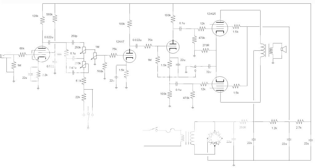
Newest design. in keeping with the low wattage bedroom amp idea I wanted to do the self-split (no phase inverter) but I also wanted some more power so I can play clean. I looked at the circuit I was using and thought with a few added parts I could convert the second triode into a Class AB with a cathodyne PI stage. Mind you that leaves me short of gain, but that was another bridge to cross later. Did the changes and tried it out. Then I started thinking (I know a dangerous thing).
Now if I add a pentode first stage I could get back my gain, that problem solved, I wanted to play with my 12AU6's anyway. Now if I use a switch and drop out the capacitor on the power tube cathodes, and then short to ground the junction of the 100k and 1.5k resistor I am back to my self-split with the PI back as a gain stage.
So rather than build two boards, one for this thread and the amp I would rather have, I get it all with adding one switch. And while I am at it, I could use the board in self-split mode, drop one tube, use a single ended output transformer, and then I have a single ended amp. I may need to adjust the output tube bias but it sure beats building another circuit if I wanted to try it.
I think this will work, I will have to try it on the weekend.
Here is my amp:
YouTube - World Champion guitar amp project - parts
And here is the demo of how it sounds:
YouTube - World Champion guitar amp project -- sounds
YouTube - World Champion guitar amp project - parts
And here is the demo of how it sounds:
YouTube - World Champion guitar amp project -- sounds
Last edited:
I thought of using a pentode input also but they have a reputation of being noisy. My plan was to use one of the triode/pentode combo tubes, Pentode section is input then the triode as a phase splitter and finally a 12au7 as a power tube. It's a cheap and easy way to get gain but you have to like that sound
Transformers are really what matters. The key is finding a good one for cheap. I have and output transformers from Triode Electronics that they sell for use as a reverb pan driver in a Fender 6G15 reverb unit. The 6G15 uses one 6K6 power tube, single ended and drives an 8 ohm pan. This would make a good and cheap amp. The 7000 to 8 ohm xformers is about $15 or so and the 6K6 tube sounds lika a 6V6 but less poer and ony about $6.00. Basically use parts from a 6G15 but place a speaker where the reverb pan would go. Thhis would use two tubes and the OPT is cheap.
I have the parts on hand and I'm building a 6G15 right now. It would be easy to try it out as an amp first but I doubt I'll get it done by the deadline. Weber also sells the same transformers but I though Triode's were a bit better
Thanks for the links Wavebourn,
I noticed you mentioned that people were copying original designs?
Is that part of the criteria for this challenge as I didn't read about that, mine is an original design, is that ok???
If people were copying original designs, that has nothing to do with this challenge. The challenge is to make the amp that is the part of the instrument and helps to produce needed sounds. The majority of "Original Designs" were looking exactly like examples from books published by manufacturers of vacuum tubes. What make them original, they intentionally had some features that made them good for electric guitars.
For example, I saw lots of Fender Champ's "Improoved Copies", but "improvements" were far from what guitarists needed to be improved. What I demonstrated today, I made the amp even worse for Hi-fi sound reproduction, but some guitar players can find it as valuable improvement.
However, another part of this challenge is to make this guitar - specific amp for less than $100 in parts.
The rest depends on imagination.
Here is my amp:
YouTube - World Champion guitar amp project - parts
And here is the demo of how it sounds:
YouTube - World Champion guitar amp project -- sounds
Damn it sounds niceeeee.....
The whole problem is that so many people have tried to skin the same cat over the years that if someone came up with something 'new' today, it probably was done at some time before by someone else. And let us face it, there are only so many ways to string together a little amp. A two or three tube amp will look like another two or three tube amp. Now will w come up with a combination of parts and design (physical layout) that someone will look at and decide they want to build? I think that is what we are trying for here right now.Thanks for the links Wavebourn,
I noticed you mentioned that people were copying original designs?
Is that part of the criteria for this challenge as I didn't read about that, mine is an original design, is that ok???
Cheers
I am experimenting with 10W 70V transformers because they are a part that is readily available and cheap enough that someone, even 10 years from now will be able to use. The rest of the circuit is just standard building blocks used in guitar amps. I will tweak the values but otherwise not too much new here.
+1 for Wavebourn's demo
BTW - what is the OPT used?
Thanks.
Both transformers come from tube radio I bought on Flea Market for $5.
The power transformer has 6.3V and 2x125V secondaries. The output tranny is 5K:8 Ohm, for 6AQ5 tube.
I think this will work, I will have to try it on the weekend.
Is the first .022uF off the first plate there to allow you to use lower voltage caps in the tone stack? It is not needed if all the caps meet the voltage spec, otherwise yes one HV cap there with say a 1 Meg bleed to gound would allow lower voltage caps in the tone stack. Also, the .022uF is in effect in series with the .1 uF and .47 uF in the tone stack at mid and low frequencies and it will dominate the reactance being of much smaller value. Fender often used .022 or .047 uF in the tone stack, did you really intend to use those big values?
Last edited:
- Home
- Live Sound
- Instruments and Amps
- The Hundred-Buck Amp Challenge