Now let's see what happens if we modify a few values to try and improve the situation.
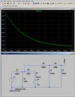
In the figure attached to this post, the circuit is exactly the same, except the values of R1 and R2 have been changed. R2, the grid stopper, is now very unusually large at 220k, fifty to a hundred times larger than what is shown on most guitar amp schematics. This large value will reduce grid current flow into the output valve.
Meantime, R1, the grid bias resistor, has been reduced to 100k, considerably lower than what is typical. This will load the phase splitter (V1) more, but will also help reduce DC voltage build up on C1 when grid current starts to flow.
The screenshot shows the result: bias still shifts, but this time, by only (-1.5) volts. This is a lot better than the (-16V) we saw in the previous screenshot! Output valve bias now shifts from (-10V) quiescent to (-11.5V) under heavy overdrive, which may be acceptable.
I am sure these simulations aren't exact - for one thing, the valve must present some additional resistance of it's own between g1 and cathode, even when grid current is flowing under positive bias. I found hints online that this resistance may be between 1 kilo ohm and 10 kilo ohms or so. Those numbers are small enough compared to R1 that they don't have a lot of effect on the outcome.
So, while these simulations aren't exact, I think they do give us some idea of the severity of the problem of bias shift under overdrive. It's a lot worse than I imagined.
And now you can see why I want to use what would be considered ridiculously large values of grid stopper resistors for the output valves - short of using direct-coupled MOSFETs to drive the grids (George's solution), this is the best solution I can come up with.
I have tinkered with clamping diodes, etc, but am not thrilled with the results. So far I haven't been able to avoid audible artifacts caused by their presence.
-Gnobuddy
Attachments
Just tried some 220k grid stoppers on my output valves (which are expected to have well under 10 pF input capacitance, including Miller capacitance). The grid bias resistors are now 100k. Coupling caps are 22 nF (same as 0.022 uF, if you have a prejudice against the "nano" prefix for some reason.) In short, component values are just like the LTSpice simulated circuit in the previous post.
The datasheet says no more than 500k resistance between g1 and ground when cathode-biased. I have 320k, so okay on that score.
It's after midnight, and I have to keep volume levels really low to avoid disturbing other people, but so far so good; I heard no audible treble loss.
I'll check again tomorrow at higher volume, as the Fletcher-Munson loudness contours tell us my ability to hear high treble isn't going to be very good at very low volume.
-Gnobuddy
Yikes! This was well into grid-current territory, I assume?...it takes several watts driving power to fully overdrive a 6L6.
My driver (phase splitter) is a little TO92 MOSFET running at about 1mA drain current. I don't think I'll get much more than a few milliwatts out of it at the most!
Transformer coupling is an interesting thought. Perhaps coupling transformers wouldn't cause any major audio problems in a guitar amp? But availability and cost are going to be issues.
I can, in fact, still find 600 ohm to 600 ohm small-signal transformers within reasonable driving distance. But these transformers are tiny little devices, probably originally designed for pocket-sized AM radios. They can probably barely handle a few tens of milliwatts, and small AM radios don't go much above 3KHz, or much below 200 Hz. I wonder if these tiddly little transformers have enough bandwidth even for a guitar amp?
On the plus side, my amp still sounds good this morning, with the 220k grid stoppers. I still have to keep the volume fairly low because other people live all around me, but I was able to turn up a little more than I did last night. I can only get just a little bit of overdrive in the current configuration, but what I have sounds decent. Looks like it's time to button up the power amp, and go back to working on the preamp again.
-Gnobuddy
600 Ohm transformers normally are limited to voltage excursions in the range of 1Vrms, not suitable to drive a tube gate.
Experiments several years ago told me that 600 ohm "telephone coupling transformers" don't work.
Just a quick update. I took the amp to a jam session (with 220k grid stoppers on the output valves), and have had a chance to hear it at normal playing volume, for about four hours.
For my ears, at least, this seems to be a good configuration. I don't hear any problems caused by the 220k grid stoppers, either for clean tones, or during overdrive.
I should add that, obviously, plenty of amp designs (that don't incorporate these very large output grid stopper values) work well, and sound good. We now know there are huge amounts of signal-induced output bias valve bias shift going on in these amps, so how do they work so well?
I think part of the reason that this happens, is that people compensate by biasing the output valves hotter - this allows them to tolerate more bias shift (towards cold biasing) without completely cutting off. But there is a price to pay, i.e. more heat and presumably, reduced lifetime for the output valves.
There is another reason, and this has to do with personal preference. With massive (cold) bias shift, comes massive crossover distortion during heavy overdrive. This presumably adds a much harsher quality to the overdriven sound - and, I think, many people actually like that more "rawkish" sound.
Personally, I like more musical-sounding/less harsh overdrive sounds, which may be part of the reason I like what I'm hearing with the 220k grid stoppers in place. (Though I'm not sure I actually heard much of a change in tone; if I did hear anything, it was towards a smoother and sweeter overdrive, though.)
-Gnobuddy
Yes, I think you are right (I am not that tube expert).
Recently I had a 100W Marshall top with a burned output xformer on the workbench. After repair I measured output power on a resistive load. Clipping on overdrive looked fine, but there was significant crossover distortion visible on the scope.
Did not like it really - just my 2c.
Recently I had a 100W Marshall top with a burned output xformer on the workbench. After repair I measured output power on a resistive load. Clipping on overdrive looked fine, but there was significant crossover distortion visible on the scope.
Did not like it really - just my 2c.
Same here, I still have a lot to learn about valves too. Such simple devices in principle, but so complex when it comes to the details!(I am not that tube expert).
I have seen oscilloscope screen captures on the 'net showing the same thing. Huge amounts of crossover distortion. I think the images I saw were taken from a Marshall 18-watt clone.Clipping on overdrive looked fine, but there was significant crossover distortion visible on the scope.
I have actually not looked at crossover distortion from my own amp on my 'scope. Part of the problem is that I really need a better signal generator than the little toy one I have now.
I understand. I absolutely hate the sound of crossover distortion in Hi-Fi amps. So does everybody else that I know! Many smart engineers spent a lot of time and effort to reduce crossover distortion to negligible levels in solid-state Hi-Fi amps.Did not like it really - just my 2c.
So how come crossover is okay (to many users) in a guitar amp? Part of the reason why valve guitar amps are interesting to me is exactly this sort of contradiction.
From the engineering point of view, there are so many things that are just terribly wrong with these old designs. And yet, we are talking about amp designs that have been hugely successful, and have been used by so many talented guitarists to make so much wonderful music. They are awful and wonderful at the same time!
I would really like to find out how to address some of the awful parts, and perhaps even make the wonderful parts a bit more wonderful in the process.
I think we have just found one piece of the puzzle, the use of ridiculously large grid stoppers for the output valves, to reduce bias shift caused by grid current flowing through coupling capacitors.
But there is an equally huge bias shift problem caused by the (shared) cathode bypass cap in the same output valves: with output devices in class AB, charge currents entering the cathode bypass cap are bigger than discharge currents leaving the cap. So we have the same problem here, the cathode bypass cap charges up, and pushes the output valves towards class C operation.
I have not found a solution for this, other than going to a fixed-bias topology. (I tried a zener clamp, it caused some ugly solid-state clipping sounds. Unacceptable.)
-Gnobuddy
Doesn't this kind of stuff add (sorta-kinda - it at least temporarily increases crossover distortion, anyway) to the power-supply-sag effect that effectively causes compression (or a drop in power after the start of a signal due to power voltage dropping under full load)?...
I think we have just found one piece of the puzzle, the use of ridiculously large grid stoppers for the output valves, to reduce bias shift caused by grid current flowing through coupling capacitors.
But there is an equally huge bias shift problem caused by the (shared) cathode bypass cap in the same output valves: with output devices in class AB, charge currents entering the cathode bypass cap are bigger than discharge currents leaving the cap. So we have the same problem here, the cathode bypass cap charges up, and pushes the output valves towards class C operation.
With all these extra imperfections (bad designs?), it's easier to see how it's been so tough to simulate tube amps in solid state. No 'real engineer' would have designed a circuit to act so badly. Besides, "people shouldn't be running these things into distortion!"
I can see the need for a data acquisition system to collect the voltage at every electrode of every tube.
I think so, too.Doesn't this kind of stuff add (sorta-kinda - it at least temporarily increases crossover distortion, anyway) to the power-supply-sag effect that effectively causes compression (or a drop in power after the start of a signal due to power voltage dropping under full load)?
Possibly worth noting: at the most recent jam, using my DIY el-cheapo amp, and no effects pedals, I could hear and feel a little bit of "squish" (compression) going on, especially when I was playing rhythm. Another guitarist commented that he could hear something like a little bit of echo/delay in my lead playing. What we were hearing sounded good, i.e., we felt these characteristics of the amp enhanced the sound. Neither effect was extremely subtle, i.e. you did not need to pretend to have "golden ears" to hear them.
I think we were both hearing dynamic bias shifts happening in my newly-redesigned amp. Something is going "squish!" in response to the initial pick attack, then rebounding.
I'm using solid-state diodes and massive filter caps in the B+ rails; there's not going to be any significant sag there.
In this particular case, I suspect the small-signal pentode in my preamp is the source of the effects we were hearing, mainly because it generates quite a lot of 2nd harmonic distortion, which you can see on the 'scope as a very asymmetrical waveform.
A very asymmetrical waveform means there is a non-zero DC component, which in turn means that a bias shift is going to happen.
This being the preamp, it's running in class A, so there isn't going to be any crossover distortion due to bias shift. But there certainly are changes in transconductance, voltage gain, transfer function curvature, and who knows what else.
Agred. Simply grabbing a convolution at one specific setting, or worse, just emulating one unchanging sigmoid-shaped voltage transfer function, isn't going to capture all these dynamic changes.With all these extra imperfections (bad designs?), it's easier to see how it's been so tough to simulate tube amps in solid state.
Too true!No 'real engineer' would have designed a circuit to act so badly. Besides, "people shouldn't be running these things into distortion!"

In my early teens I was still tinkering with the PNP germanium transistors I'd scrounged from my older brother. Somewhere I saw a valve circuit using a concertina phase splitter driving push-pull output valves. So I had the brilliant idea to implement the same circuit using my all-PNP germanium transistors, allowing me to avoid using my tiddly little coupling transformer from a pocket radio.
To my surprise, my oh-so-clever idea would work for a second, then go completely silent for several seconds, and then repeat the whole pattern, over and over.
It took me a while to figure out what was happening (I had neither scope nor meter in those days). I tried increasing the coupling cap values; it turned out, that only slowed down the process. Now the amp worked for two seconds, and then shut down for quite a while before coming back to life.
Finally, light dawned. It was the exact same bias shift problem we've been discussing on this thread. Only much worse because transistors draw lots of base current - not only when overdriven, but whenever they're conducting. Stupid me, I hadn't thought my idea through fully!
So I completely agree, this is a badly designed circuit, that just happens to work, but only if you use valves, and don't overdrive them. (MOSFETs are even better, of course.)
Agreed, I think that would be an excellent start to getting a real handle on the issue.I can see the need for a data acquisition system to collect the voltage at every electrode of every tube.
I should add that IMO this discussion is quite relevant to the $100 amp - it doesn't cost anything to design with awareness of bias shifts, and the good or bad effects they might have on the sound.
As a specific example, I'm pretty happy with the single $1 6JW8 in the clean channel of my preamp; "clean" being a bit of a misnomer, because, with a humbucker-equipped guitar, that one valve now covers the range from surf-music-clean to blues, blues-rock, and maybe a bit more; say the distorted rhythm (but not lead) guitar in The Cars "Just What I Needed". And this is not counting any additional power-amp distortion.
-Gnobuddy
A question for everyone: how do you all keep your ears honest when designing guitar amps?
I'm finding that the same amp will sometimes sound glorious (to me) one day, and "meh" a few days later. The amp hasn't changed, my subjective assessment has.
We know subjective assessment is unreliable and untrustworthy, which is why it got thrown out of good (Hi-Fi) audio engineering practice. But subjective assessment is all we have for guitar amps, n'est-ce pas?
So, how do you keep your ears honest while tweaking a guitar amp tone? Do you have a reference guitar amp you use to provide a fixed benchmark sound? Something else?
-Gnobuddy
Come back to it. After I got mine working, I left everythign as-is and it's been a few months now. After getting over the honeymoon phase I've got a bit of critical listening and ideas on how to change it. Additionally, a friend or two with a 6-pack and a few different guitars will help a fair bit!
I know these "sound fluctuations" very well. Most guitar players I know undergo these sometimes. Meanwhile I am convinced that most of the perceived sound quality is not a matter of the equipment, but more of the capability of the quitar player. So on these days when my amp sounds bad - I know I am somehow uninspired.
Last edited:
Thanks for the suggestions, jlangholzj and voltwide!
I agree that the player (me, in this case) has a big influence on the sound. Then there is the listener's state of mind (me again). If it's a beautiful summer day here in gorgeous BC, everything sounds beautiful, too...
But then there is Printer2's mini 5E3 clip, which always sounds good to me, no matter what mood I'm in. Is it just that one clip that sounds so good? I suspect not, I think Printer2 bottled some sonic magic into that amp, that I have not been able to capture in mine.
Speaking of my amp, is anyone interested in my one-bottle 6JW8 preamp schematic? I'll draw it up and post it if so. With my humbucker-pickup guitars, it goes from jazz-clean to early rock distortion (say Cream-era Clapton). My ears like the distortion better than the usual overdriven 12AX7 sound. Only real trade-off is a more complicated two-rail power supply, with roughly 300V B+ for the triode, and 150V for the beam tetrode.
The 6JW8 is still on the $1 list at ESRC as of today, by the way.
-Gnobuddy
how do you all keep your ears honest when designing guitar amps?
Gather up as many other ears as possible, preferably with different guitars and playing styles than yours, unless your amp is designed for a specific style...super clean or ultra high gain. I often loan my amps out to gather up opinions. This was easy when I worked in a plant with a few thousand people with several dozen active guitar players.
Do you have a reference guitar amp you use to provide a fixed benchmark sound?
I used to have several reference amps, back when I was actively making and modding amps. I had a black face Bandmaster, an old "Panaramic", and a black face Champ. I had a Park 1207, which is a Marshall Super Lead 100W with a different label on it.
Turbo Cha
All the amps were sold or given away when I knew that my job was ending and the big move was coming.
In the late 90's I made a dozen or so "Turbo Champs" over a 3 or 4 year period. All were compared against the "reference" Fender Champ. Every Turbo Champ was different both electrically and physically. Output tubed ranged from 6V6 to KT88 with B+ from 325 V to 450 V and power from 5 to 15 watts. Every one of them found new homes by loaning them out except for the ugly stepchild. It ran a KT88 using a power transformer from an old HP audio oscillator and a pair of JBL car speakers that I took out of my car before trading it in. The amp was too clean so that nobody I or my daughter knew wanted it. It became the practice amp in our music room. One day one of my daughter's friends brought over his ES335, plugged in and fell in love. Everyone present agreed that the amp sounded blah with the usual Strat, Mosrite, or Les Paul, but it really worked with the 335 playing rhythm. I gave the amp to him.
Now that I am basically working alone in rural nowhere where country and bluegrass is king, I will need to modify my testing methods. YouTube videos with accompanying high quality sound files will probably work.
- Home
- Live Sound
- Instruments and Amps
- The Hundred-Buck Amp Challenge