ChrisA,
I also prefer to design with a 20% margin, as this is what I learned with Texas Instruments back in the late 70s/early 80s.
That said, It does not bother me to push voltage a bit higher on caps that have a ssurge rating as most do. Some Al caps however do not have a surge rating and may even specify so.
One reason for the 20% margin is it improves the MTBF. Another is the fact that during the 70s and 80s quality sucked. We used to have to test every IC at incoming inspection to verify parameters.
Finally, the 20% margin for filter caps on the input give protection for variances in line voltage.
What is your AC input for the 460V on the caps?
I'm running 385V caps with 360 on power up with a 121VAC input. Probably not a lot of margin there either, but the caps are surge rated to 450V and once the heaters come up the B+ drops to 325V.
I posted my experience with a Nichicon electrolytic in the red board thread, but I will cover the highlights here. Pete designed a magical big red circuit board that was supposed to deliver 18 WPC. I bought one with the statement that I would be rather dissipointed if I couldn't get at least 50 WPC out of it.
50 WPC came and went within about 10 minutes of turning the thing on. I have seen 250 WPC, and posted a 125 WPC version which a few have built.
I built the board as intended except for the on board power supply. I decided I would just run the board from my bench supplies until I decided on what voltage and current levels I wanted in my extreme version. It didn't take long before I exceeded the power levels of all my supplies except for a big old HP that goes from 0 to 650 Volts at up to 1.7 Amps. Without really thinking about it I just connected the red board up to the big old HP and started turning knobs.
I had been running the board at about 600 volts for about an hour, when I decided to turn it up to 650. Before I got to the knob, there was an extremely loud bang, and a big black spot on the board where a cap used to be. The Big Dumb Blonde One was feeding 600 volts to a 450 volt cap. The power supply was capable of delivering 1.7 amps forever and quite a bit more for a half second before the limiter kicks in. With that kind of power available caps don't have time to vent, they explode!
I would allow for 10% safety factor in a tube amp especially if using 85 degree rated caps. Many caps must be voltage derated at temperature extremes.
If you are using a tube rectifier or a wimpy power transformer the cap will just vent, stink, and spray a mixture of steam and goey mess all over the place, possibly frying the tube or transformer. If working with line powered stuff or solid state rectifiers and stout power transformers the possibility of explosion is real.
Except for a few momentary lapses of reason I try to leave 20 or 30 volts of headroom in my caps.....just in case.
The clock is ticking...
And who said I do things the easy way? Forget the board and chassis I was working on, I'll get back to them later. I want to build the amp into the tabletop radio box that has been sitting around for a while, finally found the missing trim piece. A new board, just picked up some of the parts today. Same circuit as I posted last, going to do it unheard. Because I want the speaker sealed in the box, well maybe ported, I am making the chassis in the side of the box. It is in three pieces and will be screwed together. All kinds of crazy angles on the sheet metal to fit the enclosure and take up the minimum of speaker box space. The grill cloth material is a open weave placemat that I stained to give it more of a period appropriate look, along with discoloration to imitate the years gone by. I will probably miss the deadline this is going to be a crazy build, no mater this is more an experiment and an amp I wanted to build for myself. With one triode before the PI sections it will not be a scorcher, hopefully hitting some mild tones and enough volume to drive the inefficient 8". I will get back to the other designs as time permits, I really want to play with the 6AU6 some more. Some pictures.

And who said I do things the easy way? Forget the board and chassis I was working on, I'll get back to them later. I want to build the amp into the tabletop radio box that has been sitting around for a while, finally found the missing trim piece. A new board, just picked up some of the parts today. Same circuit as I posted last, going to do it unheard. Because I want the speaker sealed in the box, well maybe ported, I am making the chassis in the side of the box. It is in three pieces and will be screwed together. All kinds of crazy angles on the sheet metal to fit the enclosure and take up the minimum of speaker box space. The grill cloth material is a open weave placemat that I stained to give it more of a period appropriate look, along with discoloration to imitate the years gone by. I will probably miss the deadline this is going to be a crazy build, no mater this is more an experiment and an amp I wanted to build for myself. With one triode before the PI sections it will not be a scorcher, hopefully hitting some mild tones and enough volume to drive the inefficient 8". I will get back to the other designs as time permits, I really want to play with the 6AU6 some more. Some pictures.
Where is the cap on the voltage capacity of a capacitor?
Okay, so we've established that sending 600 Volts to a 450-volt cap is a bad idea. But it apparently isn't necessarily a bad idea right away!
And we've established that there is more than one of us that will allow ten volts over the cap's rating during warm up. At least, as opposed to ripping things apart and rewiring a perfectly good, functioning amp.
Has anyone out there ever had a "steaming stink" (or sudden disappearing act that leaves only a black spot) happen with a voltage only 5-percent over the rating (as opposed to 150 volts--33%--which we all now know doesn't work)?
How about a bad experience with an overage that only occurred during warmup? (And granted that it certainly must affect MTBF.)
I'm wondering if there isn't perhaps a 20-percent margin "built-into" the caps by the manufacturers. I've seen caps in consumer electronics that can't possibly be rated as much as 20-percent higher than the voltages they are routinely handling and almost certainly get overages during warmup.
And at what point in the supply chain I could go to lower rated caps.
The beginning of that chain uses caps that are rated at 350-volts, which is about 20-volts above anything they see, even on warmup. Down the chain, I'd prefer to switch to 250-volt caps, since the quiescent voltage at that point is lower than that, except during the worst of warmup.
I suppose I could realize some savings by going to smaller farad caps. The ones I'm using are much bigger than anything generally seen in the vintage amps.
But then, I like a quiet amp.
An answer! A REAL answer!!
YES!
Thank you!
That's what I was looking for!
I figured that someone here would intuit that.
The spec on "surge voltage" was what I was driving at.
And, yes, there is a general spec on that.
For caps with Vr (r = rated) <= 315 volts, the surge voltage rating is 1.15 x Vr
For caps with Vr > 315 volts, the surge voltage rating is 1.1 x Vr.
Surge being defined as overvoltage for not more than 1 minute for not more than 5 times per hour, as follows:
3.1.3 Surge voltage VS
The surge voltage is the maximum voltage which may be applied to the capacitor for short periods of time, i.e. up to 5 times for 1 minute per hour. IEC 60384-4 specifies the surge voltage as follows:
for VR ≤ 315 V: VS = 1.15 · VR
for VR > 315 V: VS = 1.10 · VR
(From the first document listed in the above post.)
There's my answer.
This is after only the briefest skim of the material. I'll have to read it in greater depth, but at least this a reassuring beginning!
So we DON'T have to replace those caps that go a few volts above rating during warmup after all!!!
BTW, the specs also mentioned that using the full voltage rating, DC+AC, was acceptable for continuous operation.
Which would seem to say that a 20% margin is only needed if the ripple voltage is greater peak-to-peak than 40% of the rating (which seems somehow unlikely).
And, yes, that 1000 uF / 6.3 V cap likely was engineered for use in DC filament circuits. I've been using 10 V caps, but I have both. Perhaps if the DC filament circuit was regulated . . .
Apparently, the yield of the Al EL Cap was only 92% back in 1990, but advances in the technology now has it at 98%. Similarly, upper limits to lifetime have increased 240 times since 40 years ago. (And some of us remember being old enough to drink that far back.)
I haven't gotten very far into MTBF issues in this data just yet, though. Just scratched the surface so far . . .
Overall, some very good news, indeed. And about what I expected. That's why I asked. Thanks.
And, yes, that 1000 uF / 6.3 V cap likely was engineered for use in DC filament circuits.
Maybe, but doubtful. A 6.3 volt cap would be useful in a 5 volt or less filament circuit and low voltage electrolytics were not available back when the low filament voltage DHT's were common.
Major manufacturers today will design components for use where the volume production is. We can't get a custom RF IC designed by any manufacturer even at the 500K unit per year run rate since the same manufacturer can sell into the cell phone market where the run rate is tens of millions per year.
The 6.3 volt electrolytics were most likely designed for power supplies and B+ rails for low voltage logic circuits, simple toys, hand held games, remote controls and other electronics that run low voltage battery power. 6.3 volt tantalum and ceramic parts are also common in cell phones where the battery voltage is 3.6 to 4.2 volts. All SMD stuff though.
I use 6.3 volt caps for cathode bypass in preamp circuits.
So we DON'T have to replace those caps that go a few volts above rating during warmup after all!!!......Which would seem to say that a 20% margin is only needed if the ripple voltage is greater peak-to-peak than 40% of the rating (which seems somehow unlikely).
As long as the voltage doesn't spend much time above the run rating and the unit is not repetedly turned on when hot you are OK.
Another spec that is important is the maximum ripple current. It should be in the spec for all quality electrolytics. It is likely not an issue for the typical tube amp using a tube rectifier. It often is an issue in SMPS's and can be a problem in a tube amp using a solid state rectifier and a power transformer with a low DCR, like an Antek toroid.
If the electrolytic in your power supply gets warm from the ripple current flowing through it, it will fail. It may take a year or two, but it will die. Often the caps get warm by absorbing IR radiation from the tubes. That's different.
I haven't gotten very far into MTBF issues in this data just yet, though.
MTBF of an electrolytic drops rapidly with temperature. You see ratings like 1000 hour, 5000 hour, etc. That is the average lifetime at maximum temperature. Somewhere there should be a MTBF VS temp curve. Panasonic used to publish one and there was also a lifetime derating for voltage and ripple current. When you realize that 1000 hours isn't very long for a device that sees a lot of use, you try to use 105 degree C rated caps in tube circuits and keep them away from the output tubes.
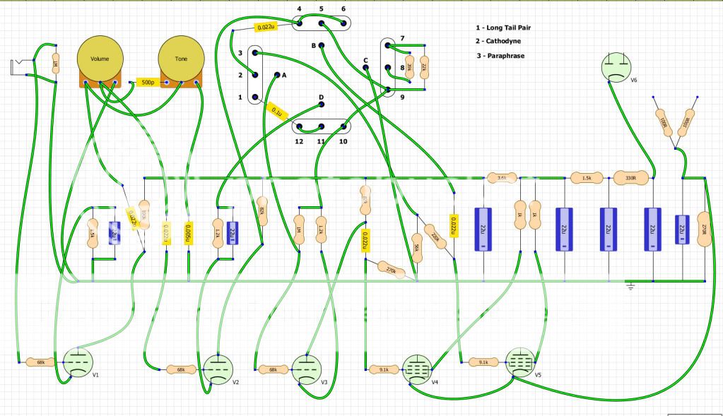
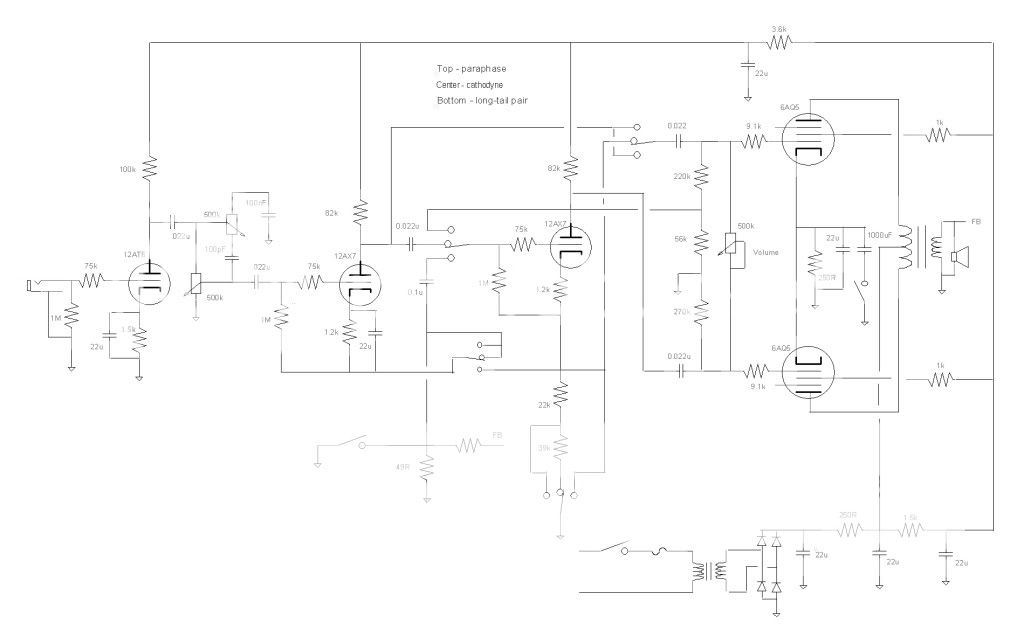
Working out the layout. Did a half baked version last night just to show the build is not that scary. The software I used did not have a four pole three position switch so I sort of made my own. I threw in a tube rectifier for the heck of it. Left out the NFB and changed the grid stopper values to 68k. Also left out the master volume and cathode capacitor and switch. Changed the pots to 1M and also the tone caps.
Last edited:
I got home last weekend just in time for some of the worst weather we have seen in a while. I planned to work on my amp cabinets last weekend, but it wasn't happening.
Florida is famous for hurricanes, but Florida also gets more tornados than any other state. Fortunately they are almost always weak and more of a nusiance than a real threat. The warnings were on the TV Sunday, Monday and Tuesday night. As usual, I ignored them. I got annoyed because the weather guy kept interrupting NCIS and NCIS-LA Tuesday yelling about SEVERE tornados. Ditto on the station 50 miles north of here. Well when I got to work on Wednesday I found out that an F2 tornado had touched down less than a mile from here destroying the homes of three coworkers. These are concrete block homes built to the strongest standards in the country.
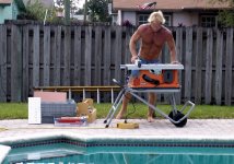
Fortunately this weekend was nice. It was about 20 degrees warmer than I would like, but you can't have everything. I got the table saw out and set up the "Back Yard Amp Shop".
I made a chassis for Amp2.2 out of leftover pieces of aluminum. I started on one for Amp1.1 but didn't finish it yet. I started a cabinet for Amp2.2 out of a leftover piece of MDF. It is patterned after a Kustom K-200 that I took apart back in 1970. They are pretty easy to make. I made several like this back in the 70's but haven't made one since, so I had to change my mind 3 times and start over once. I couldn't remember how to make it.
I wasn't smart enough to think about where the exhaust from the table saw was pointing, so tomorrow I get to clean the MDF out of the pool filter. I might have time to cover the cabinet tonight, no tuck and roll like the old Kustoms, just black Tolex.
I know the deadline is approaching fast. I don't know if either amp will be finished in time. I could just slap something together just to be done in time, but I would rather make what I want. So keep watching, both of these guys will get built, and then I will make something BIG and LOUD!
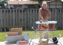
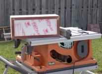
Picture 1 - Setting up the Back Yard Amp Shop. Last spring is was the Back Yard Speaker Lab. I made two sets of high efficiency horns. It's just too hot for me to work outside in the summer. The chassis containing Amp2.2 is on the far left. Amp1.1's PC board is sticking out of the Office Depot box.
Picture 2 - Sawdust is flying......right into the pool.
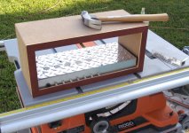
Picture 3 - The semi - finished cabinet with the amp chassis inside. I haven't made the front panel yet.
If the weather permits, tomorrow I'll cut the front panel for amp 2.2 and start on Amp1.1.
Florida is famous for hurricanes, but Florida also gets more tornados than any other state. Fortunately they are almost always weak and more of a nusiance than a real threat. The warnings were on the TV Sunday, Monday and Tuesday night. As usual, I ignored them. I got annoyed because the weather guy kept interrupting NCIS and NCIS-LA Tuesday yelling about SEVERE tornados. Ditto on the station 50 miles north of here. Well when I got to work on Wednesday I found out that an F2 tornado had touched down less than a mile from here destroying the homes of three coworkers. These are concrete block homes built to the strongest standards in the country.
Fortunately this weekend was nice. It was about 20 degrees warmer than I would like, but you can't have everything. I got the table saw out and set up the "Back Yard Amp Shop".
I made a chassis for Amp2.2 out of leftover pieces of aluminum. I started on one for Amp1.1 but didn't finish it yet. I started a cabinet for Amp2.2 out of a leftover piece of MDF. It is patterned after a Kustom K-200 that I took apart back in 1970. They are pretty easy to make. I made several like this back in the 70's but haven't made one since, so I had to change my mind 3 times and start over once. I couldn't remember how to make it.
I wasn't smart enough to think about where the exhaust from the table saw was pointing, so tomorrow I get to clean the MDF out of the pool filter. I might have time to cover the cabinet tonight, no tuck and roll like the old Kustoms, just black Tolex.
I know the deadline is approaching fast. I don't know if either amp will be finished in time. I could just slap something together just to be done in time, but I would rather make what I want. So keep watching, both of these guys will get built, and then I will make something BIG and LOUD!
Picture 1 - Setting up the Back Yard Amp Shop. Last spring is was the Back Yard Speaker Lab. I made two sets of high efficiency horns. It's just too hot for me to work outside in the summer. The chassis containing Amp2.2 is on the far left. Amp1.1's PC board is sticking out of the Office Depot box.
Picture 2 - Sawdust is flying......right into the pool.
Picture 3 - The semi - finished cabinet with the amp chassis inside. I haven't made the front panel yet.
If the weather permits, tomorrow I'll cut the front panel for amp 2.2 and start on Amp1.1.
Attachments
George, that cabinet looks great.. I'm also jealous of the nice weather you are having.. Starting to get cold here, although today was not bad..
Glad the tornado missed you.. I see the occasional waterspout in the bay a couple of blocks from our house, but that's about it..
Glad the tornado missed you.. I see the occasional waterspout in the bay a couple of blocks from our house, but that's about it..
George, that cabinet looks great..
Thanks, 5 years of evening wood shop classes should be good for something. They have taught me that I lack the patience to ever turn out something really great. 5 years of practice has allowed be to improve from really ugly stuff, to good enough.
My undergraduate degree (obtained at age 40) is in computer engineering. It also taught me that patience is required in software writing. The compiler and I used to have numerous arguments resulting in a couple of broken keyboards and a smashed motherboard! I am a hardware guy forever.
I'm also jealous of the nice weather you are having.. Starting to get cold here, although today was not bad..
Yesterday it was beautiful tourist weather, not a cloud in the sky, 65 to 70 degrees.....Today scattered clouds 82 degrees. Tomorrow?????
I was in West Virginia, Ohio, and Kentucky for the last 2 1/2 weeks. We were in northern Kentucky at about 1500 feet one night. It was about 50 degrees and raining when we went to sleep. There was 1/4 inch of ice on the car when we got up! Temperatures were between 40 and 65 the whole time, it doesn't bother me, I still ran aroung in flip flops and a t-shirt. The leaves changed from green to yellow to red to brown, to almost gone during that time. Locals say they don't remember that happening so quick in a long time, but it means an ugly winter is coming. I'll be back in December.......
Glad the tornado missed you..
So am I. I guess I'll have to listen to the loud mouthed TV weather guy more carefully, but he cries wolf so often.
This house has been visited by tornados 3 times in its 33 years. Two were minor, but one did a few $1K of damages. I was in Las Vegas for a trade show and found my house trashed when I got back. It picked up a 4 x 8 sheet of plexiglass that was leaning against the house and stuffed it through the chain link fence. The biggest piece was about an inch square.
Nice 55F (12.8C) today. Last night was supposed to be frost so I ripped out the Cayenne pepper plants and hung them in the outbuilding to dry, brought in the house plants that stay outside in the summer and covered the hydrangeas and a few others.
No frost.
George, it looks like you are having a tough time there by the pool working on those cabs (they really look nice). I bet it is rough work which requires a dip afterwards, but I'm sure you are up to it.
No frost.
George, it looks like you are having a tough time there by the pool working on those cabs (they really look nice). I bet it is rough work which requires a dip afterwards, but I'm sure you are up to it.
Caps caps
Please define "small." (For example: In a tech sheet on making a high voltage regulated supply from a garden variety LM317, there is a 2.7-Ohm resistor in series with a 1uF cap, but that is to protect the IC from surge if it's input is shorted. But I think you're talking about a bigger "small" than this, so I'm curious about what number you have in mind.)
What would you put in series with a 100uF 350-volt cap being fed "230-volt" RMS AC through a SS full-wave bridge? (I measure about 330-volts on a DVM at the input to an unloaded capacitor input filter. It comes out at about 275 volts of filtered DC after the RC Pi filter under load.)
You would put the resistor on the DC side of the rectifier, correct?
Doesn't it also reduce the DC voltage output somewhat, by virtue of that same flattening of the incoming pulse?
Adding even a small resistor in series with SS rectifiers can significantly decrease the peak ripple current, especially with low ESR capacitors. It has the added benefit of decreasing harmonic content due to charging current pulses, as it widens the pulse.
Please define "small." (For example: In a tech sheet on making a high voltage regulated supply from a garden variety LM317, there is a 2.7-Ohm resistor in series with a 1uF cap, but that is to protect the IC from surge if it's input is shorted. But I think you're talking about a bigger "small" than this, so I'm curious about what number you have in mind.)
What would you put in series with a 100uF 350-volt cap being fed "230-volt" RMS AC through a SS full-wave bridge? (I measure about 330-volts on a DVM at the input to an unloaded capacitor input filter. It comes out at about 275 volts of filtered DC after the RC Pi filter under load.)
You would put the resistor on the DC side of the rectifier, correct?
Doesn't it also reduce the DC voltage output somewhat, by virtue of that same flattening of the incoming pulse?
I bet it is rough work which requires a dip afterwards, but I'm sure you are up to it.
You know it. I only got wet 3 times yesterday. It is rare that I don't go in the pool all year round, although I don't stay in very long when the water temp is 60 degrees, or the air is in the 30's.
Yesterday it was beautiful tourist weather, not a cloud in the sky, 65 to 70 degrees.....Today scattered clouds 82 degrees. Tomorrow?????
The TV weather guy said today would be 82 degrees and sunny with a 10% chance of rain in the afternoon. When I got up it was overcast, 66 degrees and raining. I have lived here longer than any of those TV guys have been on this earth and I know you can't guess the weather in south Florida more than a few minutes in advance...it changes too quickly. It may clear up this afternoon.....or it may get worse.
In a tech sheet on making a high voltage regulated supply from a garden variety LM317, there is a 2.7-Ohm resistor in series with a 1uF cap
If you are referring to the Maida circuit, that combination is the "snubber" needed to improve the stability of the feedback loop. I found out that removing the resistor and using a film cap with a low ESR will make the circuit unstable with the sharp transients found in music.
What would you put in series with a 100uF 350-volt cap being fed "230-volt" RMS AC through a SS full-wave bridge?.....Doesn't it also reduce the DC voltage output somewhat
It will reduce the output voltage a bit. Since the diodes are conducting longer the harmonic content of the current is lower so the "crud" is easier to filter out of the circuit. If I use a resistor, I size it to lose about 5 volts. If the transformer has enough DCR, I don't use a resistor.
You would put the resistor on the DC side of the rectifier, correct?
That is the common location, but it really doesn't matter.
that cabinet looks great
Surprised here, it looks the work of a pro.
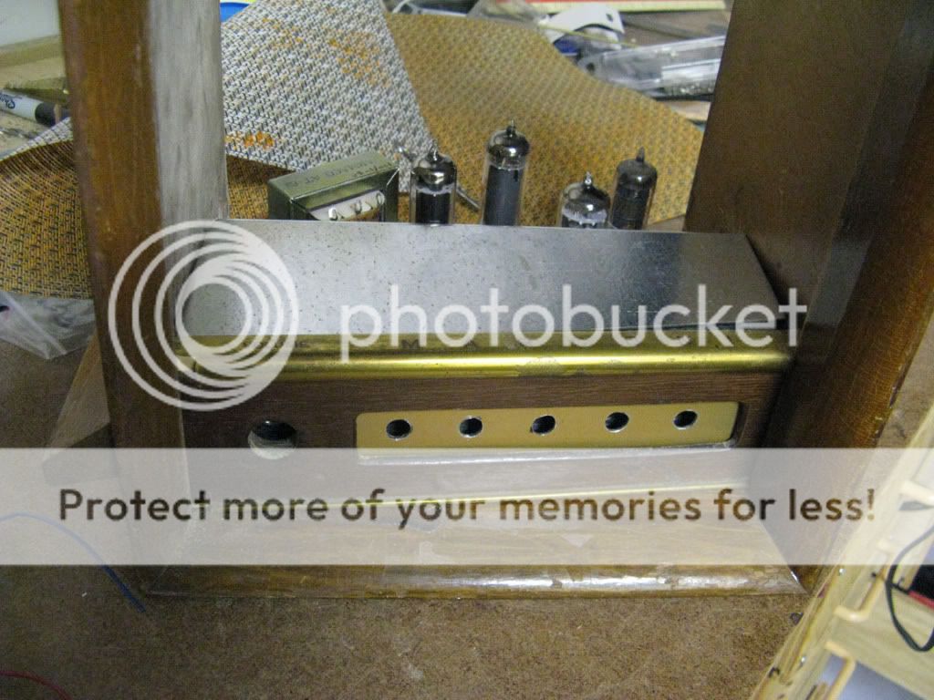
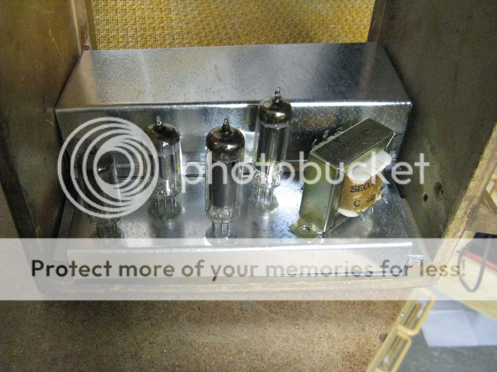
Last night I started drilling the chassis, this one gets no wood cabinet but I'm thinking it would look OK if the camouflage works - army green and cream combo. My amp got too big and with too many extras so right now I'm putting something together for the challenge. I don't think small triodes sound really good as guitar amp's output stages so I've chosen a really unusual power pentode, the EL84. LOL. But only two watts - B+ is only 180 volts. Driver tube is an 6N2N.
The chassis and the potted torodial PT comes from a power supply bought at a surplus store here in Madrid for 2 euros. BTW, I can't believe the prices, a bag with six axial 100uF/350 volts caps for 1 euro, 20 MKP 400V 2uf caps....yes, another euro. Lots of high voltage Sprague caps ridiculed priced and much much more...I'll stop here before some of you get really upset. Hehe.
PT secondaries are 15-0-15, 20-0, 20-0. I'm wiring in series the 20-0 taps to get 180 volts using a voltage multiplier. The remaining winding will feed the heaters. Maybe tonight I can post some pics.
Last edited:
Surprised here, it looks the work of a pro.
Pro photographer maybe. The camera angles are chosen to hide my screw ups. Trust me it will need some belt sander time before I can hide the minor flaws with Tolex.
I've chosen a really unusual power pentode, the EL84.
Nothing can beat the sound of an '84 cranked. I searched for a variant that I could buy for $2 and used it in push pull. The down side.....it sounds best at 20 watts!
When I walked into church this morning it was raining. When I walked out it was......table saw weather.....see you guys later, I'm going outside.
Another afternoon outside in the Back Yard Amp Lab.
First picture: The Sand Cat (small belt sander) claws and scratches her way through my bad joints.
Second picture: I cut the Lexan for the front panel. Five glowing tubes must be on display in the window! Those white flecks in the picture are the Lexan equivalent of sawdust. After that I cut a piece of aluminum. I was covered in white and silver flecks......until I jumped in the pool.
Third picture: The box is now ready for Tolex.
Now that I have remembered how to make these things (it's been almost 40 years since my last one) I made 2 more. They went far quicker than yesterday's. There is a little one for amp 1.1 that is glued together and will meet the belt sander after the glue has dried. There is a third one that was made to the size of the leftover MDF and Lexan. It isn't glued together yet since I didn't make the front fascia yet. I don't have an amp for that one yet, so I guess I'll just have to make another amp.
Attachments
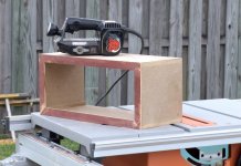

I realized that I had a few short minutes of dim daylight left, so I took the small box outside for some time with the Cat.
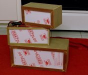
#1) Then There Were Three (where have I heard that before) The middle one is strapped together and missing its fascia (the red parts) The fascia is made out of a piece of trim that was ripped off my house during a hurricane. It has been in my garage for about 5 years, so I cut it up. Don't have enough for the third box.
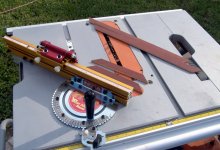
#2) The Incra is a cool tool for cutting any angle and making exact duplicates of a given length.
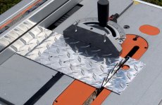
#3) I have been told not to cut aluminum on a table saw. I found that the brittle stuff cuts OK if you raise the blade so that the angle of attack is nearly perpendicular. Clean the aluminum out of each tooth of the balde after cutting with an Xacto knife.
#1) Then There Were Three (where have I heard that before) The middle one is strapped together and missing its fascia (the red parts) The fascia is made out of a piece of trim that was ripped off my house during a hurricane. It has been in my garage for about 5 years, so I cut it up. Don't have enough for the third box.
#2) The Incra is a cool tool for cutting any angle and making exact duplicates of a given length.
#3) I have been told not to cut aluminum on a table saw. I found that the brittle stuff cuts OK if you raise the blade so that the angle of attack is nearly perpendicular. Clean the aluminum out of each tooth of the balde after cutting with an Xacto knife.
Attachments
- Home
- Live Sound
- Instruments and Amps
- The Hundred-Buck Amp Challenge