Found a real odd ball 12AX7 variant, the 7058 designed for car radios with a 12 to15V
heater. Same pin out but without the center tap on the heater.
Very nice that they are ruggedized, and low noise, but they are very expensive since they
will drop into 12AX7 sockets that are wired for 12.6 V.
heater. Same pin out but without the center tap on the heater.
Very nice that they are ruggedized, and low noise, but they are very expensive since they
will drop into 12AX7 sockets that are wired for 12.6 V.
$15 is “very expensive”? Not really, just not a $3 solution. But still worth a look if trying to avoid cheap new production Russian types, and way cheaper than NOS 12AX7’s. The 12AX7 “equivalent” in a $3 (the new $1) tube does seem to be elusive. For low budget projects I’ll stoop to the level of using pentodes for small signal stages if I want gobs of gain. Just not as friendly for cloning classic guitar amp circuits.
$15 is “very expensive”? Not really, just not a $3 solution. But still worth a look if trying to avoid cheap new production Russian types, and way cheaper than NOS 12AX7’s. The 12AX7 “equivalent” in a $3 (the new $1) tube does seem to be elusive. For low budget projects I’ll stoop to the level of using pentodes for small signal stages if I want gobs of gain. Just not as friendly for cloning classic guitar amp circuits.
I was seeing them for $20 to $40 NOS, even $15 is far too much for HBC.
Right, not a $3-$5 solution.
As you are finding, just about anything that can be stuck directly into a 12AX7 socket has been run up to $10+ in price. This is especially true of tubes remotely related to audio amplification.
The 12AX7 has a Mu of 100 while the 12AT7 is 70. The 12AU7 is around 20. There are few compatible tubes with a Mu of 100, but more and more as the Mu drops.
Mu is a spec related to the maximum available gain from an amplifier stage using that tube. A typical RC coupled gain stage will reach 1/3 to 1/2 of Mu in a real world application. One can use CCS loading and mosfet buffering to achieve a stage gain approaching the full Mu of the tube, 90+% is possible, so a lower Mu tube can be used.
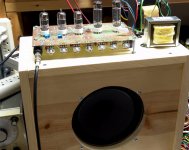
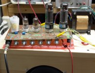
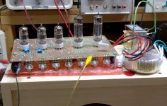
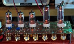
I looked back into my original HBAC directory and here is the list of tubes I was considering for the "big" amp (20 watts for just under $100). The "little" amps all used 7 pin tubes on the $1 list. All of the tubes used in my 4 watt "big little head" are STILL on the $1 list. 4 tubes, $4. OPT, $5. Power transformer. $16, all the other stuff, cheap. The chassis is the most expensive part. What's not to like.
The big amp used 9 pin tubes in odd heater voltages, all wired in series running from B+. The same tubes are available in 6 volt flavors, but some have gotten expensive since the HBAC happened.
For preamp tubes I looked at these, all have the same 9AJ pinout:
The 6BK7, 6BQ7, 6BZ7 trio (now $3 or $4) with a Mu in the 40 range. The 3 and 4 volt versions of some are still $1, wire 3 or 4 in series on a 12 volt winding.
The 6DT8 ($3) is very close to a 12AT7 (Mu of 60) without the heater tap, but the 12DT8 is now $7 or more since it fits many old radios.
The 6JK8 ($3) is an oddball, it has two different triodes inside, but both work well in guitar preamps. One has a Mu of 50, the other has a Mu of 70. There are 8 and 17 volt versions for those of us that wire heaters in series or use laptop bricks.
The tube I wound up using was the 26AQ8 / UCC85 (Mu is 50). I got a bunch from Stan for $2 each (now $4) and wired them all in series with a pair of $2 (now $5) 45B5 / UL84 which is a 6CW5 with a 45 volt heater). Unfortunately the 6volt version has been discovered by the audio world and run up to more than $15 each.
Thinking that a Mu of 50 was half that of a 12AX7, I used 3 tubes (6 gain stages) each with mosfet buffering. That turned out to be WAY too much gain, so I bypassed two or three gain stages, and removed most of the mosfet buffers. That resulted in a very useful guitar amp that's still around, but hasn't been used much since 20 watts in a concrete basement is loud. The little 4 watt amp is the one that sees constant use.
I got it all working with a real guitar amp OPT, then switched to an Antek power toroid for the OPT. I lost a watt or two in that trade, but the tone was pretty much the same.
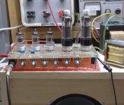
For fun I created a second board that used octal tubes. I was planning to use the 26AQ6's with some 50JY7 TV sweep tubes that I could get for $1 but someone bought all that Stan had before I got the board finished. I finished the board, and did what every guitar amp hacker would have done, cut up some traces, rewired it a bit, stuffed in some 12AX7's, and EL34's and made it into a tiny Marshall clone. It's still running 6BQ7's in the picture.
The 12AX7 has a Mu of 100 while the 12AT7 is 70. The 12AU7 is around 20. There are few compatible tubes with a Mu of 100, but more and more as the Mu drops.
Mu is a spec related to the maximum available gain from an amplifier stage using that tube. A typical RC coupled gain stage will reach 1/3 to 1/2 of Mu in a real world application. One can use CCS loading and mosfet buffering to achieve a stage gain approaching the full Mu of the tube, 90+% is possible, so a lower Mu tube can be used.
I looked back into my original HBAC directory and here is the list of tubes I was considering for the "big" amp (20 watts for just under $100). The "little" amps all used 7 pin tubes on the $1 list. All of the tubes used in my 4 watt "big little head" are STILL on the $1 list. 4 tubes, $4. OPT, $5. Power transformer. $16, all the other stuff, cheap. The chassis is the most expensive part. What's not to like.
The big amp used 9 pin tubes in odd heater voltages, all wired in series running from B+. The same tubes are available in 6 volt flavors, but some have gotten expensive since the HBAC happened.
For preamp tubes I looked at these, all have the same 9AJ pinout:
The 6BK7, 6BQ7, 6BZ7 trio (now $3 or $4) with a Mu in the 40 range. The 3 and 4 volt versions of some are still $1, wire 3 or 4 in series on a 12 volt winding.
The 6DT8 ($3) is very close to a 12AT7 (Mu of 60) without the heater tap, but the 12DT8 is now $7 or more since it fits many old radios.
The 6JK8 ($3) is an oddball, it has two different triodes inside, but both work well in guitar preamps. One has a Mu of 50, the other has a Mu of 70. There are 8 and 17 volt versions for those of us that wire heaters in series or use laptop bricks.
The tube I wound up using was the 26AQ8 / UCC85 (Mu is 50). I got a bunch from Stan for $2 each (now $4) and wired them all in series with a pair of $2 (now $5) 45B5 / UL84 which is a 6CW5 with a 45 volt heater). Unfortunately the 6volt version has been discovered by the audio world and run up to more than $15 each.
Thinking that a Mu of 50 was half that of a 12AX7, I used 3 tubes (6 gain stages) each with mosfet buffering. That turned out to be WAY too much gain, so I bypassed two or three gain stages, and removed most of the mosfet buffers. That resulted in a very useful guitar amp that's still around, but hasn't been used much since 20 watts in a concrete basement is loud. The little 4 watt amp is the one that sees constant use.
I got it all working with a real guitar amp OPT, then switched to an Antek power toroid for the OPT. I lost a watt or two in that trade, but the tone was pretty much the same.
For fun I created a second board that used octal tubes. I was planning to use the 26AQ6's with some 50JY7 TV sweep tubes that I could get for $1 but someone bought all that Stan had before I got the board finished. I finished the board, and did what every guitar amp hacker would have done, cut up some traces, rewired it a bit, stuffed in some 12AX7's, and EL34's and made it into a tiny Marshall clone. It's still running 6BQ7's in the picture.
Attachments
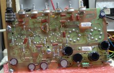

Nice work there George and thanks for the tips. Excellent looking circuit boards!
Yes, that was why I was asking about 12AT7 s, I figured Fender used 100K plate
resistors and why not just go to 220K or even a bit more. Even with the 1Meg load
of the pot we should see more gain. I've seen 12AX7 s loaded with 300K in some
Hi Fi applications.
Yes, that was why I was asking about 12AT7 s, I figured Fender used 100K plate
resistors and why not just go to 220K or even a bit more. Even with the 1Meg load
of the pot we should see more gain. I've seen 12AX7 s loaded with 300K in some
Hi Fi applications.
Just going down the list at, Antique Electronic Supply, this was just a start.
6BN4A single triode 43u 0.2A $1.95
6BK7 dual triode 40u 0.45A $2.45
6J6 dual triode common cathode 38u 0.45A $2.45
6BS8 dual triode 38u 0.45A $2.95
6HA5 triode 72u 0.6A $2.95
6AH6 Pentode $3.55
6AS5 5.5W plate 4.5k 2W, 150V $1.95
35B5
I put together a Tweed style P-P amp design there before when the contest was running. I am guessing it still can be done under $100. I wanted it all sourced in one place to keep shipping down.
Tubelab, can you show how do you do this?One can use ... mosfet buffering to achieve a stage gain approaching the full Mu of the tube, 90+% is possible, so a lower Mu tube can be used.
And what mosfet do you usually use?
Thanks.
Last edited:
I've seen that before, but I'm wondering what high voltage FET George uses and if he
uses a protection diode.
My guess is probably not the same one every time. Unless he bought 1000 of one type before EOL. You pretty much just have to search what’s available “today” to determine what to use. The ones I used for g2 regulators in my Williamson build a year ago are already NLA.
Source followers driving class A stages don’t always need gate protection diodes. For class AB I would. Power supply regulators, it’s a must.
Tubelab, can you show how do you do this? And what mosfet do you usually use?
The ideal load for an "ideal" triode vacuum tube is a constant current source with an infinite resistance and an infinite AC load impedance. None of these can be achieved in the real world, but we can do better than a resistor from plate to B+ and a cap into the next stage with its grid to ground resistor.
We can replace the plate load resistor with a CCS chip, or a discrete mosfet or BJT CCS. I have even seem vacuum tube CCS circuits used, although a mosfet is simplest and often close enough to an ideal CCS, especially in a guitar amp. I have used the little LND150 for small triode stages where the CCS is used within its dissipation limitations. Keep the LND150 to less than half a watt. The DN2540 mosfet, or IXCP10M45S CCS chip are good for more power.
This can raise the DC load to an impedance of over 1 meg, but we are still staring into the grid to ground resistor on the next stage. If that stage is a simple triode gain stage, we can often simply increase that resistor's value enough to get enough gain.
If more gain is needed, we can buffer the CCS loaded stage with a mosfet follower. Again any of the mosfet choices above apply, within the required dissipation limits.
The circuit used to do this does resemble the PowerDrive design that I use to feed output tubes grid current in AB2 operation, but for simple gain stages, big mosfets are usually not needed since we don't need to drive the next stage into positive grid operation.
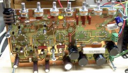
Look at the schematic for the 5 tube amp that I designed for the original HBAC. It used 150K resistors for the plate load and mosfet buffers to feed the next stage. There were 4 gain stages plus the PI. That turned out to be way too much gain. I ripped out the buffers on all but the feed to the tone stack. Ignore the mosfets on the tube cathodes. They were an experiment in variable stage gain that failed, so they were replaced with wires. I later used some e-pots to make programmable stage gain work.
Sometimes the CCS and the buffer can be combined into a single circuit, which can be built with silicon or tubes. The common SRPP design is one, though I often use a mosfet for the top tube. There is another circuit often called a gyrator that works too. I used on on the input pentode in my 4 tube HBAC redesign.
A CCS or other infinite load should be used with a triode gain stage. In theory an infinite load on a pentode will give infinite gain. In reality it can make for some serious instability, but I thought that might just be fun. It took me several weeks of tweaking to make it work, but this little 4 watt amp is the one that I use most often. See the input stage of the 4 tube amp. Try it with a triode first. This amp only runs 170 volts of B+ the mosfets are LND150's.
The 1 meg pot (R9) and the parallel combination of R6 and R7 control the stage gain. With a pentode the gain goes from mild (about 50, what you get from a typical 12AX7 stage) to wild, over 2000. At this extreme the tube gets very microphonic making for full on oscillation if the amp is sitting on top of the speaker cabinet. It will extract any hum your pickups can find, and magnify it, so C3 should be chosen to roll off the low frequency response.
The whacky single knob tone control does weird things to the mosfet load, so it is a combination distortion, treble, and bass knob all in one. These effects are minimized with a typical two or three knob stack, but I didn't have room for one in a tiny amp.
Attachments
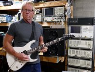
The rack and the instruments behind me are all test equipment for RF circuitry design, analysis, and testing. That's what I did for a living before retirement.
I began collecting used, and usually broken pieces of RF test equipment at hamfests and on Ebay for cheap and fixing them up. Some of these instruments sold new for over $20K each, but several years ago when places like Motorola were closing down, they were sold for a few hundred bucks or less, often in bulk and untested. I grabbed what I could when the market was flooded with excess equipment. Some of the stuff actually worked, or had minor problems. Some were parts units, used to make 2 or 3 good units out of 4 or 5 dead ones. Prices have risen since then.
I have nearly duplicated the setup that I had at Motorola when I left in 2014. The idea was to design the ultimate ham radio someday since my "employment contract" preventing such activity expired in 2015. I haven't got far down that road yet.
Behind my head is an RF spectrum analyzer, good to 2.9 GHz. The remains of the original 4 tube amp designed for the HBAC lie upside down on top of it.
To the right of that is a RF network analyzer. It is used for measuring complex impedances, loss, gain, or frequency response through any RF device or circuit. Good to 3 GHz.
On the top of the stack in the rack is a VCO/PLL signal analyzer, also good to 3 GHz. We used these for designing the RF frequency synthesizers in two ray radios and cell phones. They can measure phase noise of say the clock in a high end DAC.
Below that there is a stack of 5 similar HP or Agilent RF signal generators. These go from 100 KHz to 1 or 3 GHz. I had 9 or 10 dead ones at one time. That eventually made 7 good ones. 2 have been sold, since they fetch about $1K each. That nearly paid for all of them.
Out of the picture to the right of the rack is my RF test bench. There is a "transmitter tester" a couple RF power meters, three more RF signal generators and a modern Rigol RF spectrum analyzer capable of higher resolution measurements than the old HP.
Thanks for the answer....
If more gain is needed, we can buffer the CCS loaded stage with a mosfet follower. Again any of the mosfet choices above apply, within the required dissipation limits.
What do you think of using as a follower a more common mosfet like the IRF820, as shown by R. G. Keen on the Mosfet Follies? Is it a good option?
New low cost tube amp design
Hi
this is a design I have come up with recently. I had an old Italian 1960s practice guitar amp, Davoli brand. It was broken and needed repair. The original construction was really bad and electrically unsafe so I decided to rebuild it using the same tubes but improving the design.
This is the result:
ECH 81 preamp
EL84 single ended
Tremolo
Fender tone stack
No negative feedback
It sounds very, very nice. The tremolo is interesting, for some reason, its intensity and tone vary according to the volume setting. G3 modulation must be non linear, so for the most extreme settings you get vibrato effects, probably as a result of sideband production.
Try it, let me know what you think.
Thanks
Attachments
Thank you - it answers a few questions I'm currently breadboardingIt sounds very, very nice. The tremolo is interesting, for some reason, its intensity and tone vary according to the volume setting. G3 modulation must be non linear, so for the most extreme settings you get vibrato effects, probably as a result of sideband production.

- Home
- Live Sound
- Instruments and Amps
- The Hundred-Buck Amp Challenge