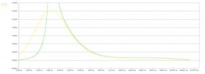
The curve cleary shows that the slope starts about 6khz and is down about 3db at around 12khz.
The curves at the top of this page look like a higher freq. I would say 3db down at about 20khz. Which will be barely audible from old tape. I would concentrate on the 100hz to 10khz region, the HF roll off is easy.
The curves at the top of this page look like a higher freq. I would say 3db down at about 20khz. Which will be barely audible from old tape. I would concentrate on the 100hz to 10khz region, the HF roll off is easy.
Yes,I was thinking that as well as it makes it diffcult to have to convert the voltage ratios in to db's.
So, That was a geusstemation from an eyeball's perspective from the shape of the curve. jer
Or a variation of !
The greatest thing is the simplicity and how easy it is to work with them without having the latency and resolution with memory capacity problems that are incurred when working with digital systems.
I have everything to do all the digital stuff.
But you just can't beat the fact of setting the mixer and hit the record button and BOOM you have your take, rarther than fussing with a mouse just to do it again and loose that moment.
That is why I love tape machines.
jer
Just for your info. Finaly figured out what the 221k resistor does. Like someone said earlier,bias. It creates a stable DC bias point for the whole circuit. Its a DC error correction circuit. If the first stage bias current increases (say from temp) the second stage current decreases which decreases the final stage current which lowers the collecter voltage which decreases the base current of the first stage.
The drawback to this is the large 10hz peak if the inputs not the right impedance.
The drawback to this is the large 10hz peak if the inputs not the right impedance.
But is this the source of the noise
I dont think so. But that much gain at 10hz in an audio circuit cant be good.
The DC resistance of the head stack is 192 ohms.
Thats fairly low, my sim shows there will be quite a big peak at 10hz with that value.
Thats fairly low, my sim shows there will be quite a big peak at 10hz with that value.
Well tape heads like loudspeakers have very different impedances at audio frequencies than their DC resistance. So its possible that the actual impedance could be several times higher.
There is probably an interaction with the input capacitance as well. This is why I was favoring the idea of a JFET at the input- the input capacitor could be eliminated in favor of a resistance to ground, which would help reduce 'head bump' which often shows up at bass frequencies. The only problem with this approach is that the original circuit has no such provision which suggests that the designer did not regard it as a problem and so its part of the sound of the instrument (if audible at all).
The other problem with that is coming up with a JFET that is actually any less noisy!
Well tape heads like loudspeakers have very different impedances at audio frequencies than their DC resistance
That was my original assumption but playing with the inductance values of the head made little difference in the sim. The freq (10hz) is probably so low it takes a huge inductance to make a difference.
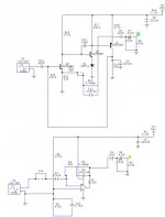
Here is what I have so far.
I don't think that the HF drop (slope) is significant to worry about.
On certain values of the 47k resistor and at 82k in the feedback loop this HF drop sarts at around 4.1khz, But the drop is very little like maybe around 1db to 2db (if that?) and flattens out as the resistor is reduced.
I still get the KV readings on the output(?).
But at least the LF slope matches the original and is very critical of the input components and the .0047uf capacitor in the feedback loop.
It is not a final draft, But it is a place to start. jer
Attachments
I was refering to the HF drop in the transistor circuit.
Even though those are older type opamps I have used them to buffer video signals aswell in the past.
The bass boost from what I have been reading is the NAB eq and this curve changes when the 100 ohm resistor is increased, and, starts to look more like NAB eq.
So I'm hoping that this will match up when hooked to the many heads.
As the input loading will change this.
Only if we knew the values of the tapeheads?
Right now this circuit needs another 2X gain to be an identical output level to the transistor circuit.
I have a PDF from analog devices that gives a good explanation of this and will post it later as I just spent the last 3 hours fixing my ethernet driver on this stupid computer.
So I didn't get to work on the design last night like I wanted to.
I was scanning alot of pictures and ran out of space.
And when I hooked my spare drive up the cable came off of the MB and by the time I got it and the BIOS changes fixed, I some how lost the LAN driver (%#^$^%#@$#)!
This is the proper EQ for nab playback and it is the oppisit for recording which what was confusing and is why there is such a bass boost.
The HF drop off seems to change by the output load and this will probably go away when I add the second stage.
This is a very easy circuit and I will do a breadbroard version to see how the noise level is, As it may be possible to create a very low noise preamp with a few stages using a proper gain structure if the first stage is to noisy due to the very high gain.
jer
- Status
- This old topic is closed. If you want to reopen this topic, contact a moderator using the "Report Post" button.
- Home
- Live Sound
- Instruments and Amps
- Mellotron preamp schematic