Hey there,
is it possible to have a cathode follower driving a tone stack, driving an effects loop aswell? connect a mono jack for the loop send from the cathode, then make a MOSFET/JFET recovery stage then go to the tone stack? or go from the treble pot to the effects send and then a recovery stage? basically i dont have room in the chasis for another valve so i need to keep it as small as possible.
Thanks for any help in advance
What amp? I would drive it from the cathode follower and return it into the tone stack using the LND150N3-G. You pop it in just the same as you would with a 12AX7, same cathode and plate values. 500v device, not bad sounding from accounts but not something you want to blast away with a lot of signal level. Mildly distorted it is said to sound OK. Better at supplying gain.
FET Preamp with LND150 Operates on Tube B+, part 1
AX84.com - The Cooperative Tube Guitar Amp Project
FET Preamp with LND150 Operates on Tube B+, part 1
AX84.com - The Cooperative Tube Guitar Amp Project
In that case how about reconfiguring the cathode follower stage as an return and use a IRF820 as the cathode follower. They are more easy to get.
IRF820 cathode follower - Google Search
IRF820 cathode follower - Google Search
hmm i might try this, though ive found a schematic very similar to what ive built, its a laney LC15 except im not using it as a push pull amp and the HT on the preamp is 250v for the whole pre amp. cathode cap values are 1uF but the attenuation between stages is about the same.
http://www.freeinfosociety.com/electronics/schematics/audio/laneylc15.pdf
i was wondering if i should copy the op amp effects loop, but im not sure what kind of swing ive got,
http://www.freeinfosociety.com/electronics/schematics/audio/laneylc15.pdf
i was wondering if i should copy the op amp effects loop, but im not sure what kind of swing ive got,
Hey there,
is it possible to have a cathode follower driving a tone stack, driving an effects loop aswell? connect a mono jack for the loop send from the cathode, then make a MOSFET/JFET recovery stage then go to the tone stack?
Yes. Better than introducing a bunch of SS devices anyways.
Yes. Better than introducing a bunch of SS devices anyways.
so going by that schematic, i can just put a jack straight from the top of that 100k resistor, then another one after it with a recovery stage?
Yes, AC coupled and attenuated with a resistor voltage divider. Gain at that node, when all is maxed, is 14000! Perhaps a loop out can be out of V1b's cathode since the signal level here is probably more usable. Even here tho you want a resistor in series, like 47kohm, to protect from a short.
I have built a couple Dumble clone amplifiers and one of his designs is a tube buffered effects loop that mates very well to his amps, many feel it is required equipment for the Overdrive Special style amp.
It uses a plated loaded input amp then a cathode follower output.
Really works well.
Originally it uses a small 135v power transformer that mounted on the outside of a single 1U rack enclosure.
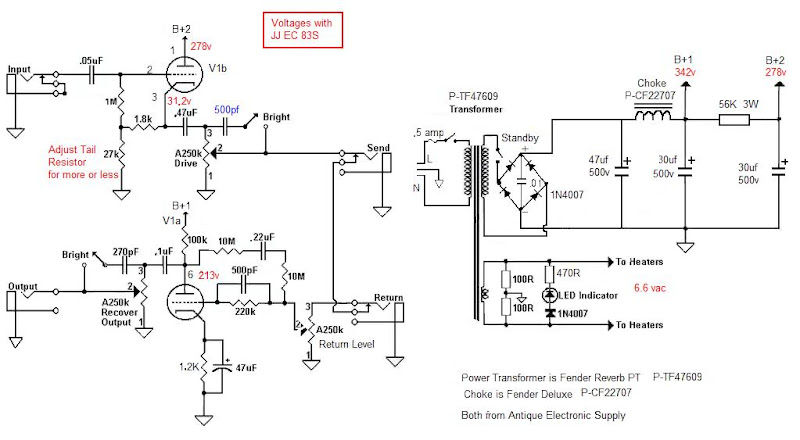
I had trouble locating that transformer so I used a PT for a Fender Reverb unit.
The original uses a voltage doubler to get the required voltage where the FX loop I built with the Reverb PT uses a bridge rectifier.
This unit is inserted between the last stage and phase inverter.
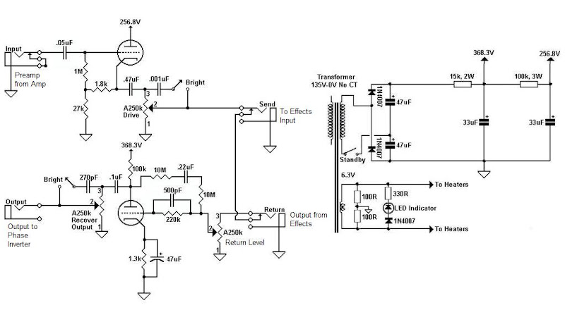
I tried a solid state FX loop before this one and it clipped the signal when the amp was up loud.
The neat thing about this loop is you can use the ouput pot as an overall master volume and you can create a pretty nice tone at bedroom levels, or crank it up to gig volume.
It uses a plated loaded input amp then a cathode follower output.
Really works well.
Originally it uses a small 135v power transformer that mounted on the outside of a single 1U rack enclosure.
I had trouble locating that transformer so I used a PT for a Fender Reverb unit.
The original uses a voltage doubler to get the required voltage where the FX loop I built with the Reverb PT uses a bridge rectifier.
This unit is inserted between the last stage and phase inverter.
I tried a solid state FX loop before this one and it clipped the signal when the amp was up loud.
The neat thing about this loop is you can use the ouput pot as an overall master volume and you can create a pretty nice tone at bedroom levels, or crank it up to gig volume.
Last edited:
Yeah that can be a problem.
But that is why I built this as a stand alone unit.
I used a large chassis and will some day put it in a smaller enclosure but,
I currently have two Dumble style amps, a 50w and 100w so this way I can use the loop with either one.
I have a TC Electronics G Sharp effects unit that sits on top and it handles the delay and reverb duties and then I also have a pedal board with the amp foot switch for overdrive and boost, a modulation pedal, chorus, tremolo, a EHX Stereo Delay, then back to the loop.
It all works very good together.
Some guys like simplicity, some like to fiddle with knobs.
I like to be able to dial in the tone I want without sacrifice.
hmm a valve effects loop separate to the amp? i like that idea, i think i might make that another project to do. thank you all very much for your help, though for this amp, i think il go with the voltage divider at the cathode follower and then a MOSFET recovery stage to the tone stack, until i have built the effects loop unit that is
- Status
- This old topic is closed. If you want to reopen this topic, contact a moderator using the "Report Post" button.
- Home
- Live Sound
- Instruments and Amps
- can a cathode follower drive a tone stack and an effects loop?