HELP!
I am not getting a signal into the board, either with a mic or line in. I've noticed the VU LED's are not functioning, and ALL peak LED's remain on constantly for all channels. No sound is coming out of the board.
All VU LED's come on when the board is first powered up, then go dark (I suppose this is correct).
Thanks!
All peak light stuck on is a classic symptom of a missing power supply voltage. The circuits run on +/-17v or thereabouts, and if one is missing, the rest of the circuit freaks 0ut.
This symptom can occur in about any mixer. On the 9000 I'd first look at the row of three-legged voltage regulator ICs inside the power supply. I bet one is bad.
This symptom can occur in about any mixer. On the 9000 I'd first look at the row of three-legged voltage regulator ICs inside the power supply. I bet one is bad.
The VU LED's appear to be functioning when the unit is initially powered up, and ALL other LEDs work. I haven't seen any which appear to be dead.
I'll have to take the cover off the PSU and test the IC's. I read a while back that folks upgrade the IC's, but can't seem to find the forum nor thread in which it was discussed.
Thanks for the replies! This is a good start!
I'll have to take the cover off the PSU and test the IC's. I read a while back that folks upgrade the IC's, but can't seem to find the forum nor thread in which it was discussed.
Thanks for the replies! This is a good start!
Either of the 17V LEDs in the master section extinquished? If so, then see Enzo's response.
I revisited the LEDs on the board. The -17v LED stays off!
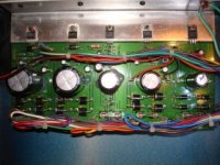
I took the cover off of the PSU, and here's what I found:
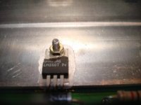
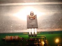
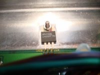
ICs 1 and 4 - Metal LM350T's with rubber/silicone insulators
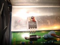
IC2 - Metal LM350T, which is chipped (from heat???) with two (2) mica insulators and thermal compound. This definitely looks like it has been replaced!
IC3 - Plastic 317/JRC/M7028J with no insulator.
IC5 - Plastic ML 7812A with no insulator.
Also, here's the # off the board: PCB815019REVB - COPYRIGHT 1997
Thanks! I hope this info helps...................
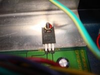
Ok, finally I'm attaching some pics of the ICs 1 through 5, and PSU board...
You can see where IC2 is chipped/broken.
You can see where IC2 is chipped/broken.
Attachments
Voltage Readings
I traced the wires from the PSU circuit board to the connector plug and took voltage readings. I'm not getting anything on pins 5 and 6 (+12v and +5v, respectively), so it would appear IC4 is the culprit. All other pins are showing correct readings.
I'm aware of the IC upgrades for these PSU's, but don't know of a supplier. :wink:
There are two separate grounds, one for the audio supplies and another for the digital/control supplies. If the supply unit is connected to the mixer they may all be connected together inside it, but not in the PS unit alone. The 12 and 5 are those digital/control supplies. 12 and 5 have nothing to do with either 17.
The IC is not chipped from heat as in heat inside the chassis, it might be chipped from heat as in the heat inside it as the silicon boiled when it failed.
Look on the board, are there not points on it labelled +17, +5, etc? And some marked as GND? If you see AGND and DGND or some variation, that indicates the digital ground versus analog ground. IN any case, on the cable to the mixer there are two ground pins, and to make measurements of the 12 and 5 outputs you need to use pin C rather than the center ground that serves the 17v rails.
I THINK analog ground is also to earth. But look on the board, doesn;t each push-on connector have a number next to it?
X1 - AGND
X3 - Earth
X5 - +18
X6 - -18
X7 - +48
Then:
X4 - DGND (along with X10,X12)
X8 - +5
X2 - +12
- Status
- This old topic is closed. If you want to reopen this topic, contact a moderator using the "Report Post" button.
- Home
- Live Sound
- Instruments and Amps
- Behringer Eurodesk MX9000 - No input/Peak LEDs stay on