This was originally a reply to an older thread.
Hello zeke and everyone in diyaudio land....
I recently converted my bogen m330a as described in this thread
http://www.diyaudio.com/forums/tubes-valves/33484-bogen-m330a-tube-pa-amp-guitar.html
...i used parts of zeke's final schematic, and I want to thank him and everyone out there for putting this information out there because the amp sounds awesome now.
I left out the nfb pot and went with the value suggested by Mike (some kind of genius)
Put in the tone stack called "fender" from a widgetlike software called tone stack calculator
Found a lot of shielded mini coax and a reverb tank in an old kenwood stereo...(had guitar inputs)
I used the top three knobs' spaces for inputs, and added two new holes for the pre-controls. my inputs squealed at first. Could have been the distance of grid resistor to socket...but i don't really know. I shielded the inputs with some wire mesh and they stopped.
any way now i have some questions and want to know if i can resurrect this string.....
see i want to include this reverb tank i pulled out of a kenwood jumbojet (kr760 i think) that was in a cccar crash....yeah....well it was just trashed...i have the tank and its driver, pickup, and all other mixing components that it needed everything is mapped out on paper......but i want to power it (b+ 30v) with something from inside the bogen....i am afraid that if i put another xformer in there i will get hum.....(which i have absolutely none!!) couldnt i just voltage drop one of the hv down to 30v and use that? the amp seems to be running a bit less than it is possible what were the "remotes" for anyway....
so there..i can post photos, schems(and mabey trade some schems too...(knight setchell carlson, and then some...)
This thing is kind of hard to distort but thats ok cause i like jazz and reggae and 60's soul and stuff....(the amp is for my guitar player anyway i play sax) and it is LOUD 30 watts doesn't describe it....
playing through a 100 watt 2x15 cab at 4ohms with vibrolux? speakers and a tele....
any ideas that could help me plumb in that reverb tank would be greatly appreciated...
by the way i am new here.
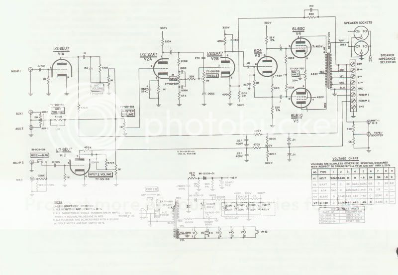
I am interested in converting a Bogen PA amp also but of a different model. It is a CHB 50 this amp has 2 6L6 for output tubes and uses 1 12ax7, 16eu7 and 1 6c4. The amp works I just converted the mic screw type fixture to a 1/4 plug and it works with my guitar, however the sound is not sweet as previously stated on the other thread. My plans are to make it a single channel input with two inputs one high gain and the other normal. I would like to use the v1b section as another gain stage and place the volume control between the v1a and v1b stages. Rework the tone stack and leave it where it is and move the master volume after v2b and before v3a.
However it has been 40 years since I worked with tubes and I sure could use some help. This amp has a lot of stuff that can be cut out and I am curious as to the Plate voltage of V1b. I am also unsure as to the correct methade to couple the stages together ie. coupling cap or nothing?
Hope I am not causing a problem by posting on this thread let me know and I will move it if necessary.
So here is the schematic of this Amp....
Well i am back and since no one seems interested i am going to make this more interesting..i ditched the jumbo jet reverberator...i rebuilt the kenwood ps exactly...the thing still sounded nasty...lots of distortion n kept blowing fets...i figured it had something to do with my ps...but i dunno...so i replaced it with a baldwin ptt1 the panoramic tone unit dual spring reverb box. I bought one on ebay with an organ tank...thinking it was its driver/pickup/mixing electronics in a nice box...turns out the "tank" was a wurlitzer tank with its own circuit, and the box was the ptt ....a dual taper spring reverb unit in a box with its own op amps to drive each spring...i found the schematic for half of the drive unit here...

it needs 22v+ I don't want to screw this up how much current do i need? can i do something with pspice? does anyone have a power supply schematic for 22v+ that will be sufficiently clean? i think the Transistor's are S429-2?
it needs 22v+ I don't want to screw this up how much current do i need? can i do something with pspice? does anyone have a power supply schematic for 22v+ that will be sufficiently clean? i think the Transistor's are S429-2?
Last edited:
First, you can get some number of volts + in a cathode biased power stage by taking the bias voltage off the power tube cathode resistor. Hammond did this for OEM outboard SS stuff late in the game.
Personally, I'd avoid 70s SS reverb drivers, they will likely not sound that great at clip. Sometimes when I need reverb in a pinch, I'll take a 1k resistor from the speaker terminal + to the + input of the tank, and the tank - can go to ground or the speaker -, depending on how they are all wired. The output goes into the second guitar jack or into a mixer somewhere in the amp. You will need a volume control, and you may need to flip the polarity of the signal somewhere to prevent huge reverb feedback.
Essentially you are taking a small sample (ideally 15v pk) of the speaker signal and running it into the tank to drive it. Then you can hook the output of the tank into an amp input, and voila, reverb. The volume control will be VERY touchy, you may need a custom taper.
Hello again I am keeping this thread here now after receiving great help in the power supply section and the musical instrument section. I went ahead and built a regulated power supply with a lm317, its pretty simple and is putting out 22v that should be very filtered. other people have been mentioning feeding a signal to the tank itself, I may try that since now i have several tanks. I would really like if the think came out sounding like the baldwin professional I know that may sound awful to any real amp afficianado, and it will never sound like the baldwin because the baldwin is not a bassman clone with 7868s and two 15s. i might be liking the baldwin box because it fits in my head cabinet, i guess i need to make some decisions based on how these things sound. before i set this up and test it i need to figure out whats happening with the plug/socket 10 pins two seem indicate that they go to the pot and switch on the diagram, BUT there are pots on the actual case, I know that there is a version without adj. maybe this patent illustration is not the best source of a schematic trying to figure out if these wires should be shorted or sent to ground..... (S2 from sideways schem above)...I am getting lost as to how much signal i need to feed this thing...i found another patent specifically for the spring, i was worried when i saw figure 7, then after reading that setup was "purely exemplary" I figured that the drive units should vibrate the spring if i simply connect a source to one of them here is the plug
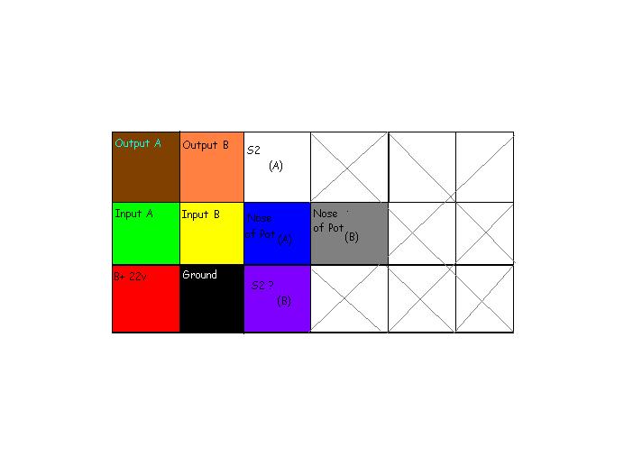
should i just jump the white and blue wires with a switch? or a switch to connect them to ground...that makes sense... the white wire goes to the 1uf cap and then tr 3 the blue comes from the nose of the pot...
should i just jump the white and blue wires with a switch? or a switch to connect them to ground...that makes sense... the white wire goes to the 1uf cap and then tr 3 the blue comes from the nose of the pot...
- Status
- This old topic is closed. If you want to reopen this topic, contact a moderator using the "Report Post" button.
- Home
- Live Sound
- Instruments and Amps
- bogen m330a -> 5f6a bassman