I have scrambled some parts and built a 50W guitar amp, Marshall style mostly.
I have some problems with cross over distortion that i can't solve, hope some one can help.
Facts: 2xEL34, OPT 3.2K, Anode Voltage 440V(!).
When i bias the tubes to about 45mA (440V * 45mA ~ 20W dissipation) i still get way to much cross over distortion.
Trace of ruffly 26W output power (into a 9.4 ohm resistor, 5V/div):
Trace of ruffly 60W output power (into a 9.4 ohm resistor, 5V/div):
Looking at older schematics and voltage charts for Marshall amps, it seems that my voltages/currents/OPT ratio is not to far off. Is this normal for Marshall amps?
Any advice most welcome!
/Mike
I have some problems with cross over distortion that i can't solve, hope some one can help.
Facts: 2xEL34, OPT 3.2K, Anode Voltage 440V(!).
When i bias the tubes to about 45mA (440V * 45mA ~ 20W dissipation) i still get way to much cross over distortion.
Trace of ruffly 26W output power (into a 9.4 ohm resistor, 5V/div):
An externally hosted image should be here but it was not working when we last tested it.
Trace of ruffly 60W output power (into a 9.4 ohm resistor, 5V/div):
An externally hosted image should be here but it was not working when we last tested it.
Looking at older schematics and voltage charts for Marshall amps, it seems that my voltages/currents/OPT ratio is not to far off. Is this normal for Marshall amps?
Any advice most welcome!
/Mike
Last edited:
Mike-
Are you using a 12AX7 as the PI?
Maybe a not well matched (balanced) 12AX7 could cause this?
[EDIT}]
I forgot bias (cold if I remember right) is the cause for this (It's been a while since I built my Marshallesque-type clone)
To answer your question, this isn't typical for any Marshall amp I've seen. Mine does
not have this issue.
Glenn
Last edited:
Thanks for your reply. Yes it is a standard long tail PI with 12AX7, taken from a Marshall 50W schematic. It looks close to perfect on my scope, so i don't suspect the PI.Mike-
Are you using a 12AX7 as the PI?
Maybe a not well matched (balanced) 12AX7 could cause this?
[EDIT}]
I forgot bias (cold if I remember right) is the cause for this (It's been a while since I built my Marshallesque-type clone)
To answer your question, this isn't typical for any Marshall amp I've seen. Mine does
not have this issue.
Glenn
I know from other tube amps that i built that correct bias removes the cross over distortion. I just can't do that with this amp, as i'll run it too hot if i do. I suspect poor impedance matching (i.e. load line), but then wonders how it could work in the standard Marshall amps?
/Mike
The tranny is "Sovtek JMP 50-2" (anyone heard about that before?). I meassured the ratio, and it is 3.2K, as should be for Marshall.Is your OT similar to the Marshall in specifications?
I run my EL34's at around 19W plate dissipation, but I'm kind of conservative.
If you look at the pictures above, you see that the dist is clearly present at only 26W output, and i could see it as low as 10W. If it indeed is magnetic saturation, could it be visible at such low power? As for the physical size/weight, it appears to be a typical 50W tranny.hello.
this kind of distortion can be caused by magnetic saturation of the opt.
lower output power should show less distortion.......some guitar amp designs use this to create a special sound.
if you do not want it you can try out a bigger opt.........
greetings........
The only thing i see out of spec is the plate voltage, that should be around 380V according to Marshall specs, while mine is around 440V. Could that be the reason (though it's such a small miss match)?
Is the bias voltage changing with applied signal?
What does it sound like when you play through it at various volume levels?
How do you calculate power? Using Vrms^2/Rload I get:
Trace1 => 24VP-P = 8.5VRMS => ~7.6W into 9.4 ohms
Trace2 => 34VP-P = 12VRMS => ~15W into 9.4 ohms
Michael
What does it sound like when you play through it at various volume levels?
How do you calculate power? Using Vrms^2/Rload I get:
Trace1 => 24VP-P = 8.5VRMS => ~7.6W into 9.4 ohms
Trace2 => 34VP-P = 12VRMS => ~15W into 9.4 ohms
Michael
Facts: 2xEL34, OPT 3.2K, Anode Voltage 440V(!).
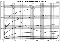
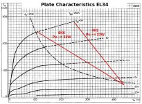
There's your problem right there. A 3K2 PP OPT works out to 800R / phase, and gives you a nearly vertical loadline. You're operating them almost Class B, so all that x-over doesn't come as any big surprise. The spec sheet for the EL34 doesn't call for a plate load anywhere close to 800R / phase.
800R / phase would be more suited to one of the TV HD finals, like a 6JN6, or a 6DC6.
Given that load, I'm surprised you haven't sent them to Red Plate Heaven.
Attachments
Last edited:
The spec sheet for the EL34 doesn't call for a plate load anywhere close to 800R / phase.
It actually does! 3,4kohm(850 Class B)/400V as presented by Philips is not far away.
But as above, rising Ua an lowering Raa is going in absolutely wrong direction
It actually does! 3,4kohm(850 Class B)/400V as presented by Philips is not far away.
But as above, rising Ua an lowering Raa is going in absolutely wrong direction
That brings us right back to the original problem, doesn't it? Class B means x-over distortion. That's why it's best reserved for RF amps, where distortion of RF cycles is filtered out by LC tuners and/or BPFs.
Audio Class B is OK for lotsawatts for AM plate modulators or PA systems where you don't care about fidelity. Otherwise, sonically, it just plain SUX.
I just want to inform about the answers I got in another forum on this issue. In fact, I (and most of the people on this forum) was totally wrong about the use of OT's in guitar amps. As the thread shows, this amps are built to run in A/B or B and that changes the math somewhat. Very interesting experience after designing Hi-Fi amps for too long 
Oh, and by the way, the cross over distortion is an important part of the classic rock sound in Marshal amps")
B+ voltage vs impedance in EL34/50W - Marshall Amp Forum
Oh, and by the way, the cross over distortion is an important part of the classic rock sound in Marshal amps
B+ voltage vs impedance in EL34/50W - Marshall Amp Forum
Last edited:
I just want to inform about the answers I got in another forum on this issue. In fact, I (and most of the people on this forum) was totally wrong about the use of OT's in guitar amps. As the thread shows, this amps are built to run in A/B or B and that changes the math somewhat. Very interesting experience after designing Hi-Fi amps for too long
Oh, and by the way, the cross over distortion is an important part of the classic rock sound in Marshal amps
B+ voltage vs impedance in EL34/50W - Marshall Amp Forum
Very interesting. What's your screen voltage? That changes the plate curves and probably explains why 3k2 works
Michael
- Status
- This old topic is closed. If you want to reopen this topic, contact a moderator using the "Report Post" button.
- Home
- Live Sound
- Instruments and Amps
- Cross over distorition in guitar amp