Hi guys I hope you can help me.... just finished building an all tube P-P EL34 guitar amp that I designed (I attached the schematic) but I'm having problems. I started building the power supply to check if everything was OK, and it was. Then I built the first stage of the amp based on a 12au7 and tested it, it worked fine.
Finally I decided to finish the entire amplifier, I turned it on and checked if the heaters were working and they were (AC 6.3V center tapped with 100 ohms resistors ala Fender), measured bias voltage and it was around -36V DC, so everything looked fine and I decided to turn the stand by switch off thus turning the amplifier on.
Immediately crackling noises were heard from the speaker and I turned the stand by switch on to avoid further damage. Then I visually inspected the circuit, nothing was burned, nothing exploded, tubes looked fine. I tried swapping preamp tubes and the same happened.
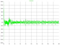
This may sound funny... the noises are like high pitched crackling noises doesn't seem to be a constant frequency hum or buzz, its hard to explain, imagine deflating a balloon, that noise, but high pitched. I haven't noticed but apparently that behaviour can be seen in the simulation as well (I attached it as well).
I'm using a custom built output transformer with a primary impedance of 3400 ohms when a 4 ohms speaker is connected to the secondary. Output tubes are Svetlana EL34's, preamp tubes are NOS 12AU7 Haltron and GT 12AT7. Everything is point to point wired.
Any advice will be appreciated. Sorry about my bad english.
Finally I decided to finish the entire amplifier, I turned it on and checked if the heaters were working and they were (AC 6.3V center tapped with 100 ohms resistors ala Fender), measured bias voltage and it was around -36V DC, so everything looked fine and I decided to turn the stand by switch off thus turning the amplifier on.
Immediately crackling noises were heard from the speaker and I turned the stand by switch on to avoid further damage. Then I visually inspected the circuit, nothing was burned, nothing exploded, tubes looked fine. I tried swapping preamp tubes and the same happened.
This may sound funny... the noises are like high pitched crackling noises doesn't seem to be a constant frequency hum or buzz, its hard to explain, imagine deflating a balloon, that noise, but high pitched. I haven't noticed but apparently that behaviour can be seen in the simulation as well (I attached it as well).
I'm using a custom built output transformer with a primary impedance of 3400 ohms when a 4 ohms speaker is connected to the secondary. Output tubes are Svetlana EL34's, preamp tubes are NOS 12AU7 Haltron and GT 12AT7. Everything is point to point wired.
Any advice will be appreciated. Sorry about my bad english.
Attachments
Double check pins 1 and 8 on octal sockets are connected. This has happened before, as 6CA7# EL34 g3 is brought out on pin 1 separately. The KT and other series has this internally connected.
I would check all socket pins; incase one has miswired. Easily done.
I am curious about the value of R1 (across o/p tranny sec)
richy
I would check all socket pins; incase one has miswired. Easily done.
I am curious about the value of R1 (across o/p tranny sec)
richy
Wavebourn said:Sounds like feedback through a ground loop. Remove all tubes except output ones, then add one by one and listen when it starts.
Hi Wavebourn, I removed the tube from the first two stages (12AU7) and turned the amp on, the problem doesn't occur. I've checked the wiring of this stages and everything looks fine. I have all grounds star connected to the first power supply cap. The input jack ground is connected to the chassis only, and the volume control ground is connected to the star ground. The volume pot case is connected to the chassis. How can I isolate the ground loop problem?
richwalters said:Double check pins 1 and 8 on octal sockets are connected. This has happened before, as 6CA7# EL34 g3 is brought out on pin 1 separately. The KT and other series has this internally connected.
I would check all socket pins; incase one has miswired. Easily done.
I am curious about the value of R1 (across o/p tranny sec)
richy
Hi richy, yes pins 1 and 8 are connected, and connected to ground.
R1 is a 4 ohms resistor, simulating a 4 ohms speaker dummy load.
Hang on.....where is the volume potty located on diagram ?
You don't have a global nfb loop; and three rc stages so gain is high, perhaps only a few mV for full o/p. Microphonics will be noticeable and depending on layout you might have to use screening cans on input tubes.
Got a layout to show ?
As you mention removing the first two tubes solves the problem..then there lies the problem.
richy
richwalters said:Hang on.....where is the volume potty located on diagram ?
You don't have a global nfb loop; and three rc stages so gain is high, perhaps only a few mV for full o/p. Microphonics will be noticeable and depending on layout you might have to use screening cans on input tubes.
Got a layout to show ?
As you mention removing the first two tubes solves the problem..then there lies the problem.
richy
The 1 Meg volume pot is formed by R18 and R32, I will draw a layout diagram to show you.
The volume pot output is supposed to be connected to a send jack (not exactly an effects loop) to connect a POD and then its output connected to the amp again via a receive jack to the second gain stage. Or if I don't want to use the POD I can connect the send to the receive jack (which is how I'm testing the amp but instead of using jacks and a cable I just connected the two stages internally).
I will try connecting directly to the second stage bypassing the first stage to see what happens.
other things to check:
- R33 & R26 should be right on the valve socket pins. Fit similar 27..47K resistors to the other 12AT7 - these 'stoppers' are to prevent oscillation!
- metal chassis should be connected to 0V (ground) at one place, preferably near the input valve/input socket.
- be sure the input socket is wired to short-circuit input to ground, when no guitar plugged in.
- try disconnecting C22/C27 to reduce gain.
- be sure wires to C19 & C24 are not too long
- be sure C19 & C24 are good quality elko, and brand new! these go bad after being stored a few years, then you get this problem (especially in reissue Fenders!)
Interesting findings
Hi Rod, I removed the 12au7 and connected a CD player directly to the input of the 12at7 gain stage, bypassing the first two stages. The power amplifier worked fine and with a minimum amount of hum.
Then I connected the secong gain stage (half 12au7) disconnecting the first stage circuit, and the same crazy oscillation occurred. But accidentally (and fortunately) I moved a cable that was near the second stage anode pin and the oscillation stopped but a significant amount of hum remained, anyway at least it was working, so I grabbed my guitar and plugged it in, now when I strum it hard the amp distorts but in an awful way. I was thinking of shielding the cables that go to the 12au7 with braid (anode, grid and cathode wire of each stage together) I will try to keep each stage cables as far as possible between them and I'll tell you guys what happen.
Rod Coleman said:other things to check:
- R33 & R26 should be right on the valve socket pins. Fit similar 27..47K resistors to the other 12AT7 - these 'stoppers' are to prevent oscillation!
- metal chassis should be connected to 0V (ground) at one place, preferably near the input valve/input socket.
- be sure the input socket is wired to short-circuit input to ground, when no guitar plugged in.
- try disconnecting C22/C27 to reduce gain.
- be sure wires to C19 & C24 are not too long
- be sure C19 & C24 are good quality elko, and brand new! these go bad after being stored a few years, then you get this problem (especially in reissue Fenders!)
Hi Rod, I removed the 12au7 and connected a CD player directly to the input of the 12at7 gain stage, bypassing the first two stages. The power amplifier worked fine and with a minimum amount of hum.
Then I connected the secong gain stage (half 12au7) disconnecting the first stage circuit, and the same crazy oscillation occurred. But accidentally (and fortunately) I moved a cable that was near the second stage anode pin and the oscillation stopped but a significant amount of hum remained, anyway at least it was working, so I grabbed my guitar and plugged it in, now when I strum it hard the amp distorts but in an awful way. I was thinking of shielding the cables that go to the 12au7 with braid (anode, grid and cathode wire of each stage together) I will try to keep each stage cables as far as possible between them and I'll tell you guys what happen.
Rod Coleman said:That sounds like a ground problem!
check that ground wires to grid and cathode are really connnected. these should all be conected together and THEN connected to the power supply 0V/GND.
Hi Rod, yes they are connected, I noticed that after turning the stand by switch off (turning the amp on) the funny fart sound is heard but it seems that after the capacitors get charged the fart sound goes away, and if I turn the volume up music gets fart distorted (as capacitors are discharged) so I will try changing C19 and C24.
I'm using cheap chinese Multicomp axial leaded capacitors, they supposed to be designed for testing purposes! Well they aren't doing their job!
Finally found the problem!
I replaced C19 first and checked, the same thing happened, then since I knew that it was a leaky or defective capacitor in that part of the circuit I just removed C22 (a cheap Multicomp axial leaded electrolytic) turned the amp on and it worked fine!
Thank you very much for all your help guys! I'll connect the first gain stage to see what happen. Thanks again.
Intermitent problem...
Well thanks to you guys I had the amp running decently for a couple of months... These are the changes I did to the original diagram I posted to lower gain since I think it was the cause of the problem:
1. Removed C27, C22 and C8 to lower gain...
2. Bypassed R8 with a 100uF IC capacitor and taken the output from R6 instead of R8. (Obviously this didn't reduce gain but it was a correction/upgrade I made to the phase inverter)
3. Upgraded C24, C19, C5 and C2 to IC 22uF caps.
These are other mods I made to reduce noise and standby switch noise (and they worked!):
1. Changed C7 and C13 to 220uF IC caps.
2. Bypassed all bridge rectifier diodes with 1KV 10nF Sprague caps.
3. Changed C15 and C16 to 330uF IC caps.
Also I changed tube layout because wires going to the tube sockets were long, and I reduced them to about 1-1/2".
The last thing I added was a pentode/triode switch.
But I'm getting the same fizzy distortion at low volumes (that I got previously if you read my previous posts), the weird thing is that the amp was running OK before the layout change and the pentode/triode switch mod. Also if the amp is running in triode mode this doesn't seem to occur, at least not at low volumes (the amp is really loud so I can't turn the volume up past its mid setting)
I was thinking to replace the 12AT7 for a 12AU7 to further reduce gain, but I'm not sure about that since the amp worked fine before and the thin distortion problem doesn't seem to occur when running triode mode. Again I hope you guys can help me I'll appreciate it a lot!
- Status
- This old topic is closed. If you want to reopen this topic, contact a moderator using the "Report Post" button.
- Home
- Live Sound
- Instruments and Amps
- DIY tube guitar amp oscillating, please help!