Hi Everyone, I need some help .....
The tube preamp section of my Crate TD-70 guitar amp has recently stopped working right after I finally bought my first decent guitar!
The solid state power amp section is still working well so I'm using the 'line out' and 'line in' to acces the power amp directly.
I've tried different 12ax7 tubes and that's not the issue. It's wierd but I get no output from the preamp and also I can't change 'channel' from A (clean) to B (dirty). The light just stays on 'A' when I press the button or even use a pedal.
Anyway, I'm about to crack it open to have a look. I'm not too experienced. I know the safety rules though. I've got an oscilloscope and a multimeter.
Does anyone have a schematic for this? Has anyone ever encountered a similar problem?
I was hoping that the channel switching thing might be a giveaway to someone.
Best wishes,
Martin.
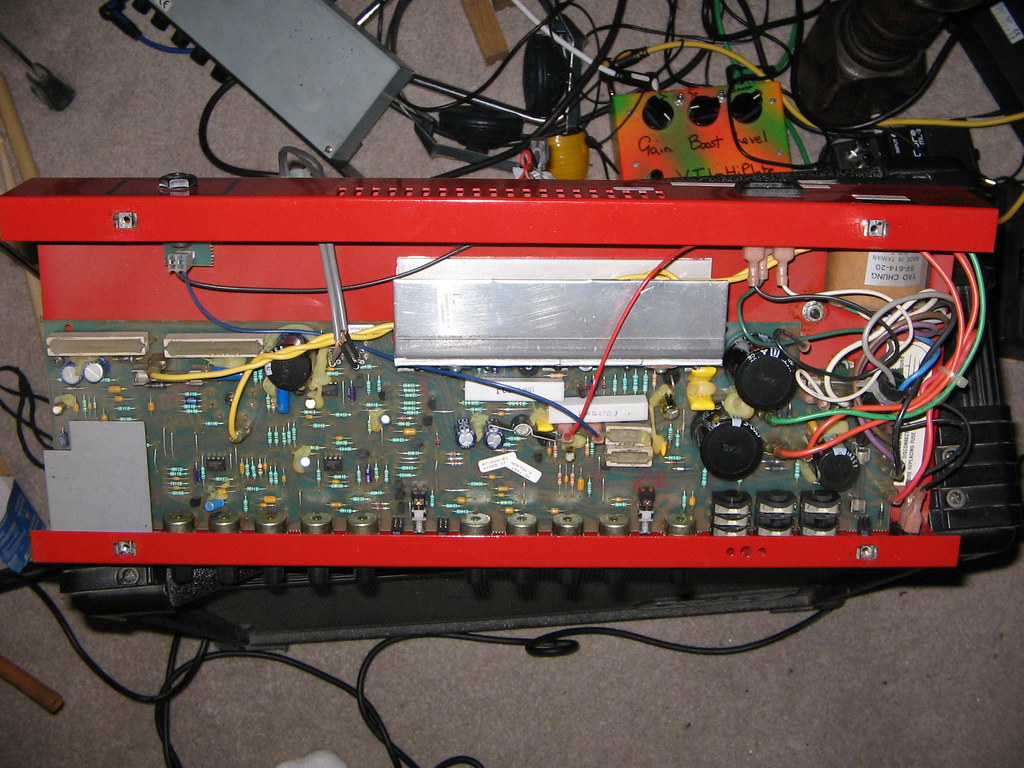
Well .... I'm still waiting for the schematic to come through so I had a peek inside:
You can see the tube pre on the left hand side and the yellow wires that come directly from the transformer. There are two zener (I think?) diodes around the fuse there. The fuse is intact and no relays are used.
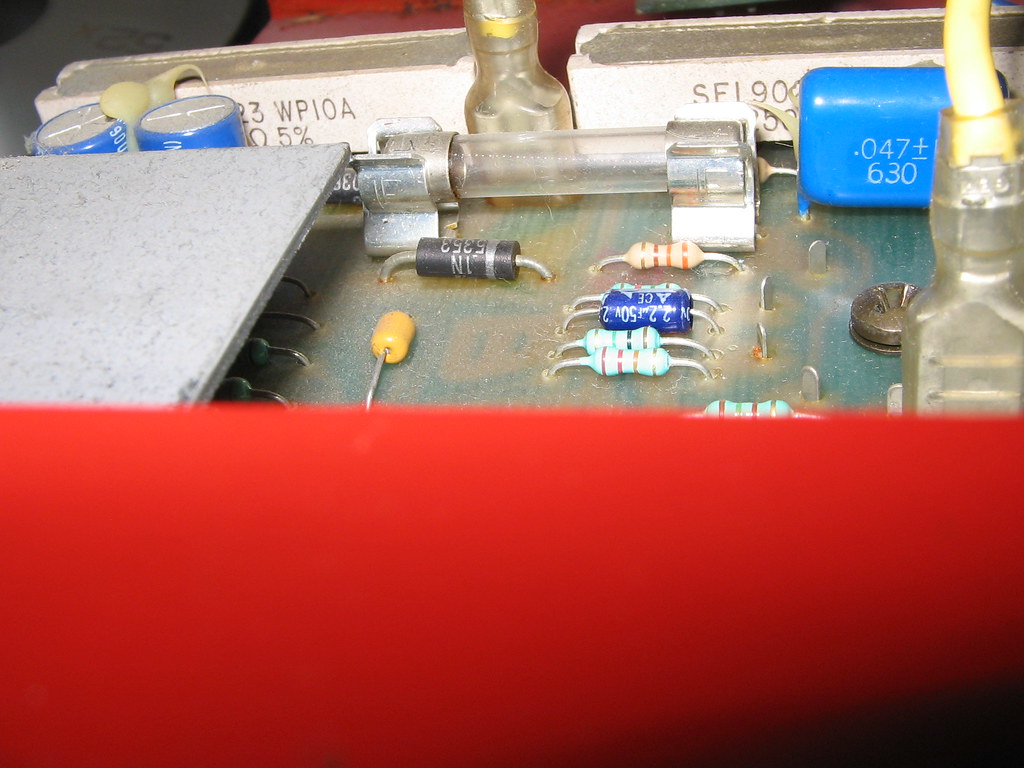
Power supply, ac enters through yellow spades:
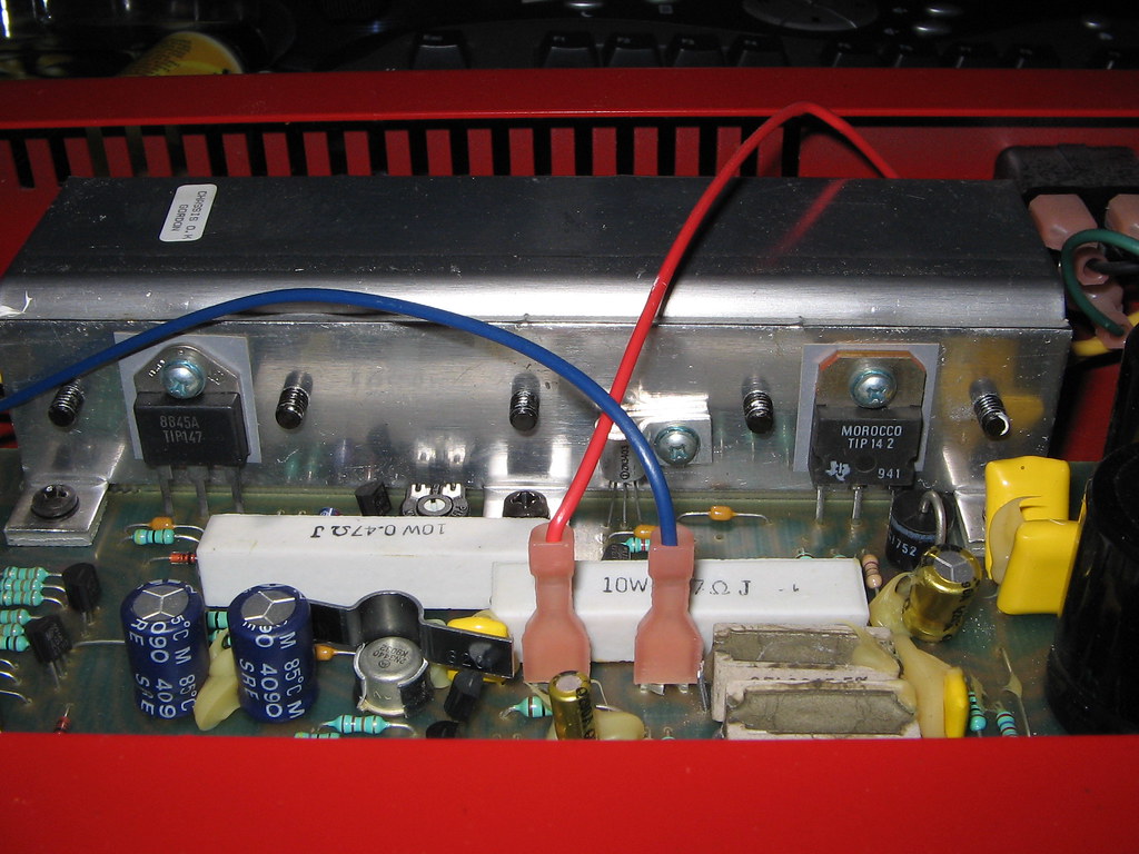
Power amp shown just for fun:
You can see the tube pre on the left hand side and the yellow wires that come directly from the transformer. There are two zener (I think?) diodes around the fuse there. The fuse is intact and no relays are used.
Power supply, ac enters through yellow spades:
Power amp shown just for fun:

Yep, the tube is glowing fine.
I've now got the schematic and I'm beginning to panic about working near 300volts !
One of the 16v zeners measures short in circuit though. Maybe I should just try replacing that first and hope for the best?
I know I should take the diode out of circuit to test first though .... I just feel a little out of my depth with such high voltage.
poynton said:What is the voltage across the zener?
I measured zero Volts across D24 when switched on. (Also 0 Ohms.)
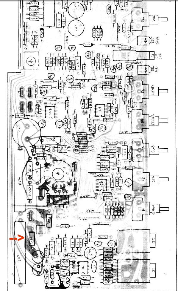
Take the offending zener out, and check it out of circuit - as you suspect it's probably S/C.
Looks like the two zeners, and the two big resistors, form the PSU for the opamp's in the preamp - and one side has gone down. If the zener reads OK out of ciruit, then you have a S/C elsewhere on that HT rail. If it reads S/C out of circuit, then it's most probably all that's wrong.
Looks like the two zeners, and the two big resistors, form the PSU for the opamp's in the preamp - and one side has gone down. If the zener reads OK out of ciruit, then you have a S/C elsewhere on that HT rail. If it reads S/C out of circuit, then it's most probably all that's wrong.
Hello, I'm the owner of a Crate alike. I found it in the garbage with no power transformer and the input tube crashed. To repair it I drew up part of the schematics. It looks like yours, and now it is working nicely, except a little problem with channel selection seemingly due of something concealed in the meanders off the switching fets circuits. Trouble I didn’t find yet.
Tube filaments are in series and supplied by the semiconductor positive power rail. So, if filaments are glowing there could be non problems with them since they are series connected.
The trouble could be caused by that zener, off course, but if it is working properly, the problem can be related to the channel and effects switching circuitry.
Best Regards.
Thanks to everyone for your good advice. I wouldn't have had the nerve to do this without your backup. I haven't had the time to test the zener out of circuit but I've ordered some replacements just in case.
Hi Larry,
Maybe mine is a bit different. The heaters seem to be fed from the yellow wires in the picture. The wires come directly from the transformer and are 6.3 VAC.
The Schematic is 1.25MB and I'd be happy to mail it to anyone that's interested.
Thanks again,
Martin.")
Larry Lomax said:..... Tube filaments are in series and supplied by the semiconductor positive power rail. So, if filaments are glowing there could be non problems with them since they are series connected. .......
Hi Larry,
Maybe mine is a bit different. The heaters seem to be fed from the yellow wires in the picture. The wires come directly from the transformer and are 6.3 VAC.
The Schematic is 1.25MB and I'd be happy to mail it to anyone that's interested.
Thanks again,
Martin.
Sonusthree said:The Schematic is 1.25MB and I'd be happy to mail it to anyone that's interested.
Hello, I would greatly appreciate you sending my the schematics, since I am right in the middle of repairing a TD-70.
Don't know so far what's wrong, the PCB got a few black spots.
However the schematics would simplify my job a lot.
Thanks in advance.
frank96@gmx.net
icebear151 said:....I would greatly appreciate you sending my the schematics ....]
Email sent. Bonne chance!
a zener should read like a diode, even in-circuit. you have two zeners here, one for the opamp + rail, one for the opamp - rail. with power applied there should be 16V across each zener. the one reading 0V is shorted. i can see from the circuit board drawing that D23 is the +16V regulator, and D24 is the -16V regulator. if R106 and R107 are both good, then R107 is probably getting a lot hotter than R106. this too is an indication of D24 being shorted. try to replace both zeners with the same voltage rating but a higher wattage rating. these appear to be 2 watt zeners, see if you can find 5 watters to replace both, this is identical to what Fender does in their amps, and these two zeners are forever shorting in Fender amps.
Big big big big thanks for all your assistance guys. Your advice was very helpful and gave me the confidence I needed to get stuck in.
Luckily, It was just the (D24) zener after all and everything is now working addictively well.
Unfortunately, I'd already fitted the regular 2 watt parts before I'd read your interesting post Unclejed. I'll definitely upgrade those parts next time I get the chance ...... or before I use it for a gig!
Well, I disassembled the heat-sink, removed the crusty old thermal grease and replaced with silver based compound. Why not? Might be worthwhile for power amp reliability. Will it make me sound cool?
How does it sound? Well, the valve-pre distortion is very alluring. I swear it's so hard to decide wether to turn the gain up or down. I've got a 12ax7 valve O/D pedal already but it's not a patch on this. Might well be because the pedal runs on 48volts (boosted from 12) and the Crate valve is on 300V. Who cares .... I love it!
The clean is just that .... clean!
I think I may just have found the courage to check the bias on the output transistors. Probably needs checking after all these years.
Thanks again for all your help, I'm very happy now,
Martin Hendrix-Clapton.
another old trick used by TV manufacturers was to solder a copper fin to the anode lead to act as a heat sink so the diode could dissipate more heat than it's rated wattage. the size of the fin would be about the size of the outside surface area of the diode (taking both sides of the fin PLUS the outside of the diode package gives 3 times as much surface area), but it would be flat and soldered on the anode lead and be sticking straight up rather than curled around the diode. philips and zenith used to do this so that they could use 2W zeners where there really should be a 5 watt device
- Status
- This old topic is closed. If you want to reopen this topic, contact a moderator using the "Report Post" button.
- Home
- Live Sound
- Instruments and Amps
- Schematic request - Crate TD-70 Guitar Amp