Great site!
I seek a cct based around a quad opamp (14 DIL), which can amplify six guitar strings (sensed via a piezo pickup in each string's bridge saddle) in order to drive a guitar->midi converter Such as this http://www.soundonsound.com/sos/oct07/articles/AxonAX50USB.htm
Here are my requirements...
1. Each opamp amp circuit to amplify a single guitar string (therefore six opamps needed, thinking of a quad opamp chip such as the TL074CN http://www.datasheetcatalog.com/datasheets_pdf/T/L/0/7/TL074CN.shtml - leaving two redundant opamps on the second chip))
2. Must be very small as I want to put it inside a guitar! (As much as I'd love it to be based on SMT, I don't have the facilities to make, so there I guess it's out).
3. Low noise.
4. A design based around a dual rail supply is fine as the 13 way midi cable from the Axon unti supplies t+ve & -ve rails.
5. Fast (by this I mean slew rate)
Some random thoughts.....
For development, I'll initally need a cct that allows variable variable gain (ie while I interface it with the aforementioned guitar-midi interface & experiment to establish what signal evel the unit likes as an input best).
The axon midi interface apparently determines the note being played by analysing transients.....
"the software uses Early Transient Recognition, which is based on neural net technology. This identifies the pitch of a note based on the characteristics of the picking transient, which in turn allows the correct MIDI note to be sent with minimal delay"
...therefore, the preamp should have a wide enough frequency response (I'm guessing) to allow not amplify the fundamental frequency but also the harmonics that plucking a guitar string yields. Therefore probably reasonable to assume that each circuit should have a reasobanle flat eq curve for all strings
Does a pcb layout/designs quad opamp exist that I can modify with 'tweaked' components as necessary?
Many thanks in anticipation,
Hank.
At the risk of talking to myself, I have a board that Roland make (which does exactly what I'm after, but it takes a magnetic pickup as an input as opposed to a piezo pickup I wish to use as an inout). I have attempted trace it out (no need to reinvent the wheel!)
Here's what I think the circuit is (uses a 4570 opamp) for each string channel (there's a dedicated pickup per string)
Does anyone recognise the type of circuit Roland are using?
Have I missed anything obvious from my attempt at tracing one channel out?
The capacitor is an unknown as it use SMT & there are no marnings on it. There is a coulour, but Google has yielded nothing to date. Here's what the capacitor looks like (C2)...
Here's what I think the circuit is (uses a 4570 opamp) for each string channel (there's a dedicated pickup per string)
An externally hosted image should be here but it was not working when we last tested it.
Does anyone recognise the type of circuit Roland are using?
Have I missed anything obvious from my attempt at tracing one channel out?
The capacitor is an unknown as it use SMT & there are no marnings on it. There is a coulour, but Google has yielded nothing to date. Here's what the capacitor looks like (C2)...
An externally hosted image should be here but it was not working when we last tested it.
An externally hosted image should be here but it was not working when we last tested it.
Hi,
Is what your after a simple Op-Amp based amplifier, low noise, wide bandwidth etc. That's easy !
The problem is I have no idea what sort of signal a guitar pickup outputs (amplitude etc) or what the characteristics of one are. Is it a low impedance device of only a few ohms. If you know what the amplitudes are that it puts out at max and what level you need we should be able to come up with something suitable.
Regards Karl
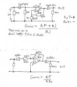
Edit, I have attached the following. I drew this a few days ago for another posting but it seems relevant to what you need.
Simple Opamp gain stage, you can see how to calculate the gain you need. The first stage is non inverting, the second inverting.
Is what your after a simple Op-Amp based amplifier, low noise, wide bandwidth etc. That's easy !
The problem is I have no idea what sort of signal a guitar pickup outputs (amplitude etc) or what the characteristics of one are. Is it a low impedance device of only a few ohms. If you know what the amplitudes are that it puts out at max and what level you need we should be able to come up with something suitable.
Regards Karl
Edit, I have attached the following. I drew this a few days ago for another posting but it seems relevant to what you need.
Simple Opamp gain stage, you can see how to calculate the gain you need. The first stage is non inverting, the second inverting.
Attachments
As Mooly said, we would need to know the characteristics of your pickups, including at least the approximate maximum output voltage level and the output impedance. Failing that, you could possibly test a pickup, maybe with an attenuator and then a variable-gain opamp amplifier, and probably deduce the needed information. Or, if you have an oscilloscope, it might be simpler. Alternatively, if you have the make and model of the pickups, or of the piezo element (if there's no intervening circuitry), we might be able to find the necessary data online.
Regarding the schematic you gave: It doesn't appear to be a typical amplifier. It might work as a comparator (i.e. banging to one rail or the other). Are you sure that the opamp inputs aren't the opposite of what you've shown?
Regarding the schematic you gave: It doesn't appear to be a typical amplifier. It might work as a comparator (i.e. banging to one rail or the other). Are you sure that the opamp inputs aren't the opposite of what you've shown?
Apologies for not responding sooner, but I've been busy researching.
I've changed guitar so my needs have changed!
Could someone tell me the best way to effectively actively split a piezo (which has a very high output impedance) using a unity gain non inverting opamp, into identical signals, both signals these identical will then go on to feed circuit boards that the piezos were designed to feed directly....
HI Z -> splitter circuit (unity gain) -> original cct board
. -> original board.
Since both the board the piezo was originally feeding were designed to be matched with the piezo I seek to split, I don't need any amplification.
I realise there's an abundance of unity gain op amp circuits about, but my head hurts wrt the output impedance of the opamps feeding into the two (original) boards & specifically how/where to 'Y' the signal off from one into two.
Many thanks in advance!
Thanks for bearing with me thus far.
I've thrown the Roland board away (too much hassle!) & started making my own board. Rather than spam the board with new threads, I though it'd be best to tack my latest questions on the bottom of my original thread!
I now intend using a non inverting opamp circuit (dual supply as the rails can easily be sourced from the the unit I'm interfacing guitar with) ...which will need a gain of upto 8 (I intend using a variable resistor to set the exact gain required & then replace with a standard resistor...this will make the circuit more compact).
My question.
If you look at these two simple circuit diagrams here...
http://www.radio-electronics.com:80/info/circuits/opamp_non_inverting/op_amp_non-inverting.php
The basic circuit has no AC coupling capacitor
Whereas on that same page further down the AC coupling circuit obviously has.
Now bearing in mind my input will a guitar piezo pickup....I'm not sure if I need a design with AC coupling ?
If I do need AC coupling, then this article suggests my final circuit will need a bias resistor...
http://www.audiodesignline.com/howto/204201786
See section one "Common problems " 1) Failure to provide a DC bias-current return path when using AC coupling
Below the diagram in that section is this statement...
"In this circuit, a resistor is connected between the op-amp input and ground, to allow the input bias currents to flow. For lowest input-offset currents using bipolar op amps, R1 is usually set equal to the parallel combination of R2 and R3"
I'm not understanding what they mean by "the parallel combination of R2 and R3" (I understand what parallel resistance is & how to calculate it!)...but in their diagram the resistors R2 & R3 in series?!
Also I'd need R1 to be at least 1M ohms (so as not to load the piezo pickups)...where does that leave me wrt their statement for the values of R2 & R3 (& bearing in mind I need a gain of 8)
Finally does it matter how I achieve a gain of say 8. In other words is it better to use higher resistances in the feedback loop (eg 800k & 100k to get the gain of 8) or smaller resitances (eg 8k & 1k)...or does it matter not?
Many thanks....loving this forum!
I'm not understanding what they mean by "the parallel combination of R2 and R3" (I understand what parallel resistance is & how to calculate it!)...but in their diagram the resistors R2 & R3 in series?!
It's exactly as it says. Treat R3 as if it were going to ground as well, which it is basically for dc analysis.
Also I'd need R1 to be at least 1M ohms (so as not to load the piezo pickups)...where does that leave me wrt their statement for the values of R2 & R3 (& bearing in mind I need a gain of 8)
R2 will be a bit more than 1meg and R3 will be 8 times higher. Will just have to do the math to find what values you need.
Finally does it matter how I achieve a gain of say 8. In other words is it better to use higher resistances in the feedback loop (eg 800k & 100k to get the gain of 8) or smaller resitances (eg 8k & 1k)...or does it matter not?
Ideally you want to use as low of values thats practical to keep noise low. Since you have already defined what it has to be in the previous statement, you don't really have much choice.
Many thanks - all points were duly noted.
I've built/tested the board - it seems to work fine.
I'd now like to split the signal (actually there'll be six indidiual signals but for the purpose of simplicity, I'll just refer to one).
The chain will look something like this...
IP -> Non inv Opamp -> ? -> Output A
-> Output B (to be summed with 5 others of the same characteristic)
The ? above is becuase I don't know what to use!
What I'm trying to achieve is 'Y' off (split) the signal. One leg of the signal is to feed a device that must receive this signal in isolation ...the other leg must feed a 'circuit' that combines this leg with 5 others of the same type.
I'm sorry if that doesn't read well (it's difficult to describe clearly in words & I have no way of getting a diagram posted up her at the moment).
when I look at the circuit of a typical summing amp, eg...
http://www.ecircuitcenter.com/Circuits/opsum/opsum.htm
I don't think I can use a simple passive resitor way of connecting all the B outputs (ie from the description furtyher above), as I'm figuring this woulkd lead to the A output (again as described above) having an element of interference/crosstalk ...call it what you will.
therefore I'm thinking it will need this...
IP1 -Non inv opamp-> A output (to remain 'pure')
-> B output ->inv opamp-> summing amp.
IP2 -Non inv opamp-> A output (to remain 'pure')
-> B output ->inv opamp-> summing amp.
IP3 -Non inv opamp-> A output (to remain 'pure')
-> B output ->inv opamp-> summing amp.
& so on....up to 6 inputs (one for each of the guitar strings)
The output of the summing amp would give me one signal...which would be a combination of all the inputs. I can then send this down a standard guitar lead to a normal guitar amplifier.
I guess my question here is do I need to buffer the B output leg via the second inverting opamp described in the chain above in order to keep the 'A output ‘pure’, or can I just take the ‘B’ output straight to a summing amp (cutting out the second inverting opamp).
- Status
- This old topic is closed. If you want to reopen this topic, contact a moderator using the "Report Post" button.
- Home
- Live Sound
- Instruments and Amps
- tiny opamp based cct to amplify six (piezo) guitar pickups?