SE 6550 class project (continued)
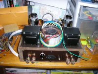
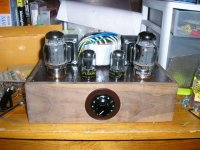
Here are some progress pics from an earlier thread that I posted about a month ago. I was just doing an impromptu "fit-up"- and decided to post these. The base still needs finishing- and the ins/outs need labeling.
Comments, criticisms, etc??
Here are some progress pics from an earlier thread that I posted about a month ago. I was just doing an impromptu "fit-up"- and decided to post these. The base still needs finishing- and the ins/outs need labeling.
Comments, criticisms, etc??
Attachments
The schematic...................
Thanks for your kind coments.
The schema is located on this thread...............
http://www.diyaudio.com/forums/showthread.php?s=&threadid=118313&highlight=se+kt88
There are some minor errors on the schematic because this was the first draft, so please forgive me.
It uses a ccs-loaded 6sn7 that yields a gain of about 14. I am using a heavily modded Adcom GCD-750 that puts out about 3 volts peak. The simulation shows that within it's practical power range, the circuit yields roughly 3% THD. I am considering adding a pentode switch as well.
The volume knob came from a 50's automobile radio. I machined a disc to fit the numbered dial inside because it looked a bit stark without it.
Re: SE 6550 class project (continued)
I would not use a toroidal power transformer. Any hash or noise from your power line will make it right through. Just an opinion.
cadaverdog said:Here are some progress pics from an earlier thread that I posted about a month ago. I was just doing an impromptu "fit-up"- and decided to post these. The base still needs finishing- and the ins/outs need labeling.
Comments, criticisms, etc??
I would not use a toroidal power transformer. Any hash or noise from your power line will make it right through. Just an opinion.
About the toroid....................
I was worried about EM radiation being that the chassis was so small. The EMI self-cancellation properties of the toroid appealed to me in this particular design.
I wish that I had time to do a couple of build-ups both with an EI lamination transformer and with the toroid. Unfortunately, I have to present a working prototype before the class in 2 weeks.
I would not use a toroidal power transformer.
I have the same Antek toroid on a SimpleSE. No problems with noise even with an electric drill plugged into the same outlet as the amp (one of my usual amp torture tests). I am using a choke in my power supply though. You can hide a Triad choke under the chassis at a later date if needed.
The problem that I see is the B+ voltage. I get about 500 volts using solid state rectifiers with this transformer. I am using cathode bias so the tube sees less voltage. With about 485 volts across the tube (assuming 15 volts lost in the DC resistance in the OPT) you will need about -50 volts of bias. (based on my Electro Harmonix 6550's)
Woah!!
One of the things not present on the schematic is the fact that I bumped-up the supply voltage to 400VDC, but that admittedly doesn't come close to 500VDC!!.................scary.
With that being said, I bench tested this transformer by measuring the secondaries with a true RMS DVM and got about 410V, then I measured the leg to leg dc resistance and saw about 52 ohms. I entered the values into a simulator and "virtually" loaded the supply with 2K ohms. The sim shows about 408 + or - a few volts and about 190ma.
I'm hoping I come reasonably close to that because I don't care to blow up those $25 Panasonic caps!!
BTW, Thanks for the warning.
I'd be worried about overstressing your Tungsol 6550 as well. Make sure you don't exceed their dissipation ratings under your chosen operating conditions.
I'd also make up a nice cover for the toroid, nothing worse than the unfinished look of a toroid on top of the chassis to cause people to focus on the appearance of your project rather than on its performance. I've had this unfortunate experience and actually lost the opportunity for a commercial contract because the focus ended up on the appearance of my engineering prototype rather than on its superior sonic performance relative to its competition.
I'd also make up a nice cover for the toroid, nothing worse than the unfinished look of a toroid on top of the chassis to cause people to focus on the appearance of your project rather than on its performance. I've had this unfortunate experience and actually lost the opportunity for a commercial contract because the focus ended up on the appearance of my engineering prototype rather than on its superior sonic performance relative to its competition.
Actually.................
............The perforated metal you see in the background of the picture is going to be used as a transformer cage. It'll have wood end caps- and be painted the same shade of "chocolate."
On that note, I believe that an audio equipment should look just as beautiful as it sounds. I had this image in my mind of a 50's looking amp, but with a few modern goodies such as the toroid and the soft recovery diodes, etc.
It was hard to get a cool "utilitarian" look, yet still retain some elegance; that's pretty much why the cage is for covering up the butt-ugly toroid- yet leaving the bottles exposed.
Thanks for your suggestions, they are greatly appreciated!!")
PS, I ruined several machine tools when I milled the stainless top-plate. My suggestion is to stay away from this material for DIY!!
............The perforated metal you see in the background of the picture is going to be used as a transformer cage. It'll have wood end caps- and be painted the same shade of "chocolate."
On that note, I believe that an audio equipment should look just as beautiful as it sounds. I had this image in my mind of a 50's looking amp, but with a few modern goodies such as the toroid and the soft recovery diodes, etc.
It was hard to get a cool "utilitarian" look, yet still retain some elegance; that's pretty much why the cage is for covering up the butt-ugly toroid- yet leaving the bottles exposed.
Thanks for your suggestions, they are greatly appreciated!!
PS, I ruined several machine tools when I milled the stainless top-plate. My suggestion is to stay away from this material for DIY!!
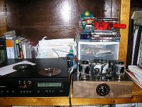
I have recently completed the project shown in this thread:
http://www.diyaudio.com/forums/showthread.php?threadid=120919&highlight=
I have to present it before the class on Tuesday.
In my opinion, the amp sounds wonderful (even through my dorm-mates non-hi-end KLH bookshelf speakers.)
Anyway, I found myself getting way too bogged down in things like clipping symmetry, when the voltage swing in the preamp stage (w/line level input) could never get that high in the first place!!
The assumption that the one-half 6sn7 configured as a CCS would protect the input from crosstalk and noise turned out to be dead-on. Channel seperation (not measured, just perceived) is absolutely fabulous.
The only thing I don't like is the 6mV of 60Hz hum appearing at the outputs. The only thing I can imagine it being is the fact that the filament supply has no center tap and is essentially floating. I am going to make one tonight out af a pair of 100-Ohm resistors and see if I have any luck.
After presentation, I will probably pull-apart most of the wiring I've done (as the layout is a bit sub-optimal.)
I highly suggest that you build one as it really does sound wonderful.
The only thing I don't like is the 6mV of 60Hz hum appearing at the outputs. The only thing I can imagine it being is the fact that the filament supply has no center tap and is essentially floating. I am going to make one tonight out af a pair of 100-Ohm resistors and see if I have any luck.
Another thing you can try is to rig a voltage divider across B+ and ground. Set the divider for about 60 V. Connect the +60 VDC to 1 side of your filament winding. Connect that same side to ground via a high value/100 WVDC 'lytic.
Yes, it's definitely OK to combine the 2 techniques.
I took a quick glance at the pics and didn't see a schematic. Sorry if it's there and I missed it.
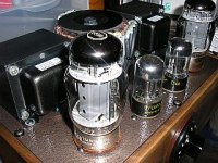
So from the pics it looks like a 6SL7 driving a 6550. ... any of the high gain driver tubes are more prone to AC power supply noise than their lower gain counter parts.
IF this is used with a computer or newer CD, you might be able to get by with a 6SN7 driver, which should have an easier time driving your output tube and have less noise as well... all without getting fancy... may not even have to change up the circuit...
Also, 6millivolts of noise is really not that bad... look/listen to some old school kit and you will be wondering how you thought it was loud! Not to mention at normal listening distance and levels - 8-10ft with 90db speakers... it's not loud enough to be heard... or your 6 millivolts reading is off. :^)
great looking amp... hope this has started years of tube enjoyment.
let's reiterate... that's .006V on your meter... thats not much.. and for the sound you should be getting, a quieter amp is not always better!
Actually...................
Those are 6sn7's. One half of each of them is biased as a CCS @ about 8mA.
I got a chance to listen to the amp tonight on my friends 108dB Klipsch speakers- and I'm impressed so far.
There is a touch of "hand over mouth" muffling in general; I suspect that the culprit is the PIO coupling caps (they tend to round off a bit.)
I have some .056 uF Russian teflons that I'm going to try next.
I'll keep you posted.
Yeah when I looked at the other thread again... I thought, eh, those plates are a little bigger than I thought... so I figured maybe as much.
Still, that noise figure seems reasonable to me... are you using feedback at all to get the hum down? was I wrong? Did I miss the schematic?
Still, that noise figure seems reasonable to me... are you using feedback at all to get the hum down? was I wrong? Did I miss the schematic?
Here's the schematic...................
There's no feedback.
This is the most current version of the amp. The only difference is a different PT with no center tap- and a bridge rectifier made with Hexfreds.
http://www.diyaudio.com/forums/attachment.php?postid=1440544&stamp=1204136901
I am taking suggestions as to grid resistor sizing, however.
Any comments??
- Status
- This old topic is closed. If you want to reopen this topic, contact a moderator using the "Report Post" button.
- Home
- Live Sound
- Instruments and Amps
- 6550 SE class project (continued)