As many of you know I am in the process of building a guitar amp. I had the turret board all laid out and then did some further reading on grounding and I think I may need to change the approach that I am using.
I would like your opinions on this.
On Paul Ruby's web site he discusses grounding extensively and I found the following.
That seems to indicate that the circuitry for the various stages should be interlaced with the filters for that section while I have it laid out with all power supply filters on one end of the board with the circuitry on the other end. BTW, I am using star ground.
What I have is...
(left to right)
input circuitry==>second gain stage circuitry==>Tone Stack and PI circuitry==>output tube circuitry==>input filter==>second gain filter==>PI filter==>screen filter==>PS input cap.
What he seems to be indicating is that it should be
(left to right)
input stage circuitry==>input stage filter==>second gain stage circuitry==>second gain stage filter... and so on.
I can see where the second layout might make more sense for keeping power connections short and keeping high current sections away from low level sections.
Would you agree that the "interleaving" is a better approach?
If so I have a slight wrinkle in that I am using two dual section caps 33uf (one cathode connection two anode connections each) and one single cap 30uf. As I have it wired now I use the single cap as the input cap and the others for the following stages.
What I think I would do in trying to implement the interleaving system would be to use one dual cap for the plate and screen supplies as both of those circuits will be the most immune to noise and both are relatively high current. Then use the second dual cap for the PI and second gain stage and the single cap for the input stage so that it can be as isolated as possible from the others.
So it would look like...
(right to left)
Output tube plate and screen supply cap(s)==>output tube cathode grid pulldown resistors==>PI and gain stage caps==>PI and gain stage circuitry==>input stage cap==>input stage circuitry.
What do you think? Should I change to this configuration?
mike
I would like your opinions on this.
On Paul Ruby's web site he discusses grounding extensively and I found the following.
Your board layout should have the following basic layout running either right to left or left to right:
PT-HV, recto and first filter cap; Power amp and second filter cap; final preamp stages or PI and filter cap; initial preamp stages and filter cap.
That seems to indicate that the circuitry for the various stages should be interlaced with the filters for that section while I have it laid out with all power supply filters on one end of the board with the circuitry on the other end. BTW, I am using star ground.
What I have is...
(left to right)
input circuitry==>second gain stage circuitry==>Tone Stack and PI circuitry==>output tube circuitry==>input filter==>second gain filter==>PI filter==>screen filter==>PS input cap.
What he seems to be indicating is that it should be
(left to right)
input stage circuitry==>input stage filter==>second gain stage circuitry==>second gain stage filter... and so on.
I can see where the second layout might make more sense for keeping power connections short and keeping high current sections away from low level sections.
Would you agree that the "interleaving" is a better approach?
If so I have a slight wrinkle in that I am using two dual section caps 33uf (one cathode connection two anode connections each) and one single cap 30uf. As I have it wired now I use the single cap as the input cap and the others for the following stages.
What I think I would do in trying to implement the interleaving system would be to use one dual cap for the plate and screen supplies as both of those circuits will be the most immune to noise and both are relatively high current. Then use the second dual cap for the PI and second gain stage and the single cap for the input stage so that it can be as isolated as possible from the others.
So it would look like...
(right to left)
Output tube plate and screen supply cap(s)==>output tube cathode grid pulldown resistors==>PI and gain stage caps==>PI and gain stage circuitry==>input stage cap==>input stage circuitry.
What do you think? Should I change to this configuration?
mike
Distributed - what you have called interleaved works best. It also distributes the decoupling resistors and so you are not dissipating a lot of power in just one place. Its always best to have the power supply decoupling capacitor right where its being used.
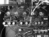
I've attached a picture of a recent guitar amp build - part way through construction. The board at the top of the picture is the preamp board, the board at the bottom of the picture is the power amp board. You can clearly see how the power supply capacitors have been distributed to the points where they are actually used.
I hope this is of some help.
Cheers,
Ian
Attachments
- Status
- This old topic is closed. If you want to reopen this topic, contact a moderator using the "Report Post" button.