Hello everyone.
I would like to do some home recording, so i had an idea of DIY interface suitable for guitar or microphone connection and better then usual el-cheapo onboard soundcard.
And here is what it looks like:
Mic----------(MicPreamp)-------->PCM2900 channel1
Guitar------(GuitarPreamp)---->PCM2900 channel2
So, its basically a 2-channel (PCM2900 is stereo) ADC connected over USB to the PC.
For the Mic preamp i would use following schematics: http://sound.westhost.com/project66.htm
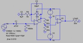
And for the guitar preamp, i had to design a little myself (see attachment).
Now, CRITICS and SUGGESTIONS are greatly APPRECIATED, since i used textbook approach for guitar preamp without audio experience.
I would like to do some home recording, so i had an idea of DIY interface suitable for guitar or microphone connection and better then usual el-cheapo onboard soundcard.
And here is what it looks like:
Mic----------(MicPreamp)-------->PCM2900 channel1
Guitar------(GuitarPreamp)---->PCM2900 channel2
So, its basically a 2-channel (PCM2900 is stereo) ADC connected over USB to the PC.
For the Mic preamp i would use following schematics: http://sound.westhost.com/project66.htm
An externally hosted image should be here but it was not working when we last tested it.
And for the guitar preamp, i had to design a little myself (see attachment).
Now, CRITICS and SUGGESTIONS are greatly APPRECIATED, since i used textbook approach for guitar preamp without audio experience.
Attachments
I have used that Mic preamp design before and it sounds pretty good but I think you can do better and with less Parts, I would suggest looking at the INA217/THAT1510 Mic preamp IC"s...they are very low noise and can be implemented in a simular way to a regular opamp and the data sheets have curcuit examples Pluss designing a PCB for the mic preamp would be a lot easier than the one you are looking at....
As for the Guitar preamp curcuit I can see a few potential problems....
First you should have the input impedance set to about 1m ohm not 1k5, Guitar pickups are high impedance, so I would switch the 1k5 resistor for a 1m resistor this will also set the frequency of the input filter to somewere arround 20hz...
Also you only have the Gain at about 2x ,You might want more especially for guitar pluss you have no tone controlls or overdrive which are pretty much needed in a Guitar preamp.....
I would maybe suggest increaseing the Gain to at least 10x and to enable a switchable overdrive you can simply add a couple Opposite Faceing Diodes from the output to ground....
You can also use the Second opamp as your tone controll curcuit by adding a couple filters to the feedback loop in an Inverting config.....
Good luck
Hi Minion, thanks for reply.
It is definitely worth looking at INA217/THAT1510. But unfortunately they are not easily accessible here in Germany. What i found is SSM2019, which is even pin-compatible with THAT1510. I can buy those SSM2019 for about 6 Euro here.
Otherwise, i would substitute TL071 for NE5532 (about 0.80 Euro) and build Project66, as intended.
What do you think about SSM2019?
Now, for guitar preamp there is a 1500k resistor there. Which makes 1.5M, should be good enough. It's just a weird notation that i used (1500k).
I am not sure about distortion, i have recently built a tube amplifier with nice tone, so for recording it will be micked (here comes in that microphone preamp). Guitar preamp is only for clean, no overdrive.
Tone stack is a good idea, probably will be implemented.
Also, how much gain should i have, i dont want to overdrive the input of PCM2900. Some pickups are quite hot, circa 1.2Vpp and consumer line level is about ~0.3Vrms, if i'm not mistaken.
By discrete he means only useing Passive components (Like Transistors and caps and resistors and no opamps) the front end of the Mic preamp schematic you posted is Discrete....
When going discrete you usually have to do a more complex circuit layout than when useing Opamps......
The SSM2019 is a Good Chip for a Mic preamp ,They are drop in Replacements for the THAT 1510 and the INA217 preamp chips and have simular noise specs.......
I guess if you are going into a ADC you don"t want the levels very hot so a Lower gain is probably a better idea but you will only get a very clean sound which I guess is ok for acoustic type stuff.....
Good luck
Well, discrete design would be interesting from the theoretical point of view and perhaps for other DIYers here. Problem is, i'm not that good in advanced circuits  .
.
So, for this time i would have to use chips.
Then the configuration would be following:
Mic preamp ---> SSM2019 (perhaps also tone controls?)
Guitar preamp ---> above schematics with implemented tone controls (baxandall??), no overdrive, based on NE5532 opamp.
Regarding ADC, PCM2900 is sort of a ready soundcard chip with USB interface and Line level inputs. Uses standard driver and requires very few extra components. The question is to select correct gain in this case, as info about line levels are confusing and not always follows specs.
. So, for this time i would have to use chips.
Then the configuration would be following:
Mic preamp ---> SSM2019 (perhaps also tone controls?)
Guitar preamp ---> above schematics with implemented tone controls (baxandall??), no overdrive, based on NE5532 opamp.
Regarding ADC, PCM2900 is sort of a ready soundcard chip with USB interface and Line level inputs. Uses standard driver and requires very few extra components. The question is to select correct gain in this case, as info about line levels are confusing and not always follows specs.
t_blizzard said:So IC it is. Great!
Any questions regarding line levels?
They differ from consumer to pro-audio.
Doesn't make any difference really, you stick a pot on it anyway, so have a wide range of adjustment - and it's not much different in any case.
My main concern was about input level of PCM2900. It say that it is a line level, so i assume consumer line level, which is 300mV rms, as much as i know. But it is not allways true somehow.
Another idea is to integrate a overload/peak detector. So when the input of PCM2900 is overloaded, LED would light or so. Are there some simple solutions for that? Or perhaps LED VU meter or so?
Also tone controls would be good for mic preamp.
Another idea is to integrate a overload/peak detector. So when the input of PCM2900 is overloaded, LED would light or so. Are there some simple solutions for that? Or perhaps LED VU meter or so?
Also tone controls would be good for mic preamp.
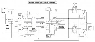
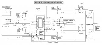
Multiplex Audio Overdub Schematic
I spent the day designing this Multiplex Audio Overdub Schematic ... It's based upon a Quad TL072 Op Amp and 2 LM386 Low Power Audio Amp Integrated Circuits ... It has Mic/Elec. Guitar Hi-Impedance Inputs (L-R) with adjustable gain up to 10X ... Tandem Universal Aux/Line Inputs/Outputs after the gain stage ... It then feeds into a 'buffer' stage that allows Computer headphone output mix to the final LM386 Amps for Stereo Output ... I had planned on this for quite some time and finally got around to it !!!
I spent the day designing this Multiplex Audio Overdub Schematic ... It's based upon a Quad TL072 Op Amp and 2 LM386 Low Power Audio Amp Integrated Circuits ... It has Mic/Elec. Guitar Hi-Impedance Inputs (L-R) with adjustable gain up to 10X ... Tandem Universal Aux/Line Inputs/Outputs after the gain stage ... It then feeds into a 'buffer' stage that allows Computer headphone output mix to the final LM386 Amps for Stereo Output ... I had planned on this for quite some time and finally got around to it !!!
Attachments

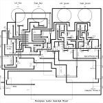
This is the updated version with a printed circuit board layout ... this is the reason for the additional jumpers on the schematic ... to maintain a single layer bottom trace on the pc board. Board dimensions are 5" x 5" ... etching would require a mirror image of the board ...
Attachments
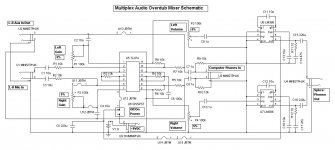
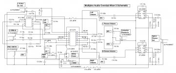
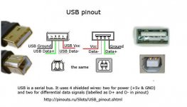
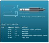
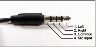
Here is an updated version with better buffer isolation by adding a dual op amp for guitar imput ... notice that the input is monaural (one channel) yet the output is stereo (2 channels) to alleviate the guitar plug/jack cancel of one channel ... the printed circuit board layout in previous thread is top side to scale ... not mirror image for etching ... will design a pc of this version A.S.A.P. ... Also, these (as many of my musical/audio do-it-yourself projects) are experimental SPICE designs and have not been physically built and tested. Although, I have been active in Audio Electronics for nearly fifty years and design with SPICE based primarily on hands-on experience of many previous constructed stomp boxes and etcetera. Additionally, I reduced the voltage to +5VDC and it worked in a simulation run just fine ... This is typical USB (Universal Serial Bus) Voltage ... A standard USB has four connectors ... The outside connectors are +5VDC and Ground, respectively and the two inner connectors are for data processing! SEE IMAGE ... also included is an image of a standard phone plug pin out ... This applies generally to both 1/8" and 1/4" versions of plugs and jacks.
Attachments
Last edited:
I just noticed another 'typo' in one of my threads (imput instead of "input") ... can be difficult trying to post when the site shuts your post down with no further edit allowed while multitasking ... was editing images and ... oops? Main reason I haven't been here for awhile and shun websites that don't allow later edit/delete of post/thread ... I can spell almost every word in a Webster's Dictionary ... bye.
Last edited:
- Status
- This old topic is closed. If you want to reopen this topic, contact a moderator using the "Report Post" button.
- Home
- Live Sound
- Instruments and Amps
- Guitar USB preamplifier/interface