Hello,
I'm a noob to this forum, and also to circuit design. I'm also interested in a specific project and I thought I'd try to glean a bit of information about the right way to do things.
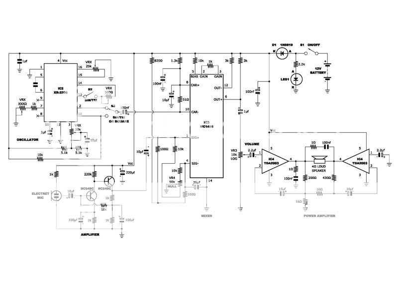
This is a ring mod circuit I knocked up. I freely admit I've just done a bit of web scouring to get it. The sub-circuits for the waveform generator, the modulator and the power amp are straight off the manufacturer's data sheets. The mic pre-amp I have used is from Andy Collinson's design. I am awaiting his permission to use this and I will not go ahead without his say-so.
The aim of the project is to make a portable and battery powered Dalek voice mod. The Dalek sound is basically a ring modulator, but most Dalek builders require a small, self-contained unit. My basic circuit will be an XR-2206 (providing the carrier waveform) mixed in with a voice signal. This will be modulated in an MC1496 balanced modulator/demodulator before being amplified via either a TDA2005 or bridged twin TDA2003s to give about 20W output. Eventually, I will need to make the dome-lights flash in time with the operator’s speech too.
I'm a noob to this forum, and also to circuit design. I'm also interested in a specific project and I thought I'd try to glean a bit of information about the right way to do things.
This is a ring mod circuit I knocked up. I freely admit I've just done a bit of web scouring to get it. The sub-circuits for the waveform generator, the modulator and the power amp are straight off the manufacturer's data sheets. The mic pre-amp I have used is from Andy Collinson's design. I am awaiting his permission to use this and I will not go ahead without his say-so.
The aim of the project is to make a portable and battery powered Dalek voice mod. The Dalek sound is basically a ring modulator, but most Dalek builders require a small, self-contained unit. My basic circuit will be an XR-2206 (providing the carrier waveform) mixed in with a voice signal. This will be modulated in an MC1496 balanced modulator/demodulator before being amplified via either a TDA2005 or bridged twin TDA2003s to give about 20W output. Eventually, I will need to make the dome-lights flash in time with the operator’s speech too.

This may seem a very basic question to most, but don't forget - I'm new to all this. What's the difference in application between polyester (greencaps), MKT and electrolytic capacitors? The circuits I have just show a capacitor, but looking into existing circuits where I can actually see the components, there is a mixture of the two sorts. How does one decide which type to use? Is it just a case of trial and error, or are there certain types of circuit that inherently require certain caps? 
Same question for metal film resistors. I've seen one designer say to use metal film resistors, but I don't know the difference to know why.
Can anyone shed any light?
Same question for metal film resistors. I've seen one designer say to use metal film resistors, but I don't know the difference to know why.
Can anyone shed any light?
actually, i can think of a simpler way to get the sound you're looking for. i'll work on a schematic for it and post in a day or so. all it uses are a 4049 hex inverter as an oscillator, and an op amp and a 4066 cmos switch for the modulator. i don't even know if the XR2206 is even available anymore......
basically what the circuit i'm thinking of does is switch between inverting and noninverting at a rate determined by the carrier frequency, much like the MC1496 does. it's not as clean a modulation as the 1496 produces, but then again, the dalek voice isn't cleanly modulated either. it definitely would sound the same as using the xr2206 square wave to modulate the 1496, and with about 20% of the parts count.
as far as choices of caps go.... here's my 2 cents..... it's an effects box producing intermodulation distortion, so you don't have to be choosy with the cap types
Thanks for that Unclejed. I'm sure there are many ways to achieve a decent Dalek voice in a simpler way that I am trying. This is actually the first time I have tried any kind of electronic design, so I'll expect my first attempt to be either massively complicated or just simply unworkable.
I've had a look at other builders attempts and they seem to have four basic areas; microphone preamp, oscillator (Dalek voices will need a triangular or possibly sine waveform, variable between 20 and 80Hz), modulator and a power amp.
I can get the XR2206 from Farnell here in the UK, although now you've said it might be rare, I may have to get it sooner rather than later. http://uk.farnell.com/jsp/Semiconductors/Signal+Conversion/EXAR/XR2206CP-F/displayProduct.jsp?sku=1095815
I was going for this IC as it gives out pretty much all waveforms, so I can have a good play to get the best effect.
For the modulator, I have been advised to look at an LM13700N as this has been previously used by other builders and it produced a good effect.
I looking forward to seeing what you come up with.
Phil
Unclejed613,
Your idea for a circuit jogged a memory. A while back, I bought a voice mod kit from Dick Smith in Australia called a Vader Voice. It's been deleted now, but I found a circuit diagram for it (reprinted from Silicon Chip magazine). It too uses the 4066, but it uses a 7555 as an oscillator, which also gives out a square-waveform carrier. The practical difference is that the square wave carrier makes you sound more like an original series Cylon than a Dalek.
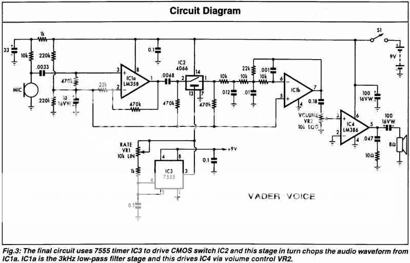
To "convert" the kit to produce a Dalek voice, the VR1 pot needs to be changed from 10k linear to 1M linear. The oscillation rate is too high as the kit stands and this gives you the option of turning it down (Daleks need around 40Hz or thereabouts).
I'm still going to have a go at my own, but I'll be using the MC1496 as it's a proper modulator. I've been told the 4066 uses a bilateral switch. I have no idea at all what that is but I know I need a modulator and the 1496 is one of those 
In the meantime, I'd still be interested in your design, and it sounds like others would be too.
Phil
Your idea for a circuit jogged a memory. A while back, I bought a voice mod kit from Dick Smith in Australia called a Vader Voice. It's been deleted now, but I found a circuit diagram for it (reprinted from Silicon Chip magazine). It too uses the 4066, but it uses a 7555 as an oscillator, which also gives out a square-waveform carrier. The practical difference is that the square wave carrier makes you sound more like an original series Cylon than a Dalek.
To "convert" the kit to produce a Dalek voice, the VR1 pot needs to be changed from 10k linear to 1M linear. The oscillation rate is too high as the kit stands and this gives you the option of turning it down (Daleks need around 40Hz or thereabouts).
I'm still going to have a go at my own, but I'll be using the MC1496 as it's a proper modulator. I've been told the 4066 uses a bilateral switch. I have no idea at all what that is
but I know I need a modulator and the 1496 is one of those In the meantime, I'd still be interested in your design, and it sounds like others would be too.
Phil
Since you modulate with a rectangular anyway you might as well use a "polarity switcher" around and opamp and a 4066. For the clock genrator you may use a logic gate with schmitt-trigger input. Even tough you have an IC that you only use up to 1/4 you will only have to add two components a resistor and a cap:
http://www.fairchildsemi.com/ds/CD/CD4093BC.pdf
Regards
Charles
http://www.fairchildsemi.com/ds/CD/CD4093BC.pdf
Regards
Charles
the "polarity switcher" is exactly what i was talking about. with a logic 0 on the control input the circuit is noninverting, with a 1 it is inverting. with an audio frequency square wave it is a simple ring modulator. the difference between this and the vader voice is that the waveform is not chopped on and off, but switched between inverting and noninverting, a more subtle, but still very audible effect.
the difference between this and the vader voice is that the waveform is not chopped on and off, but switched between inverting and noninverting, a more subtle, but still very audible effect.
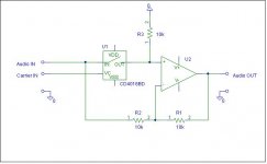
It won't even be difficult to make a thingy that can be switched between both modes.
Below you can see how it can be done. The positions of U1 and R3 can be interchanged theoretically. But I would leave it where it is because the analog switch doesn't make a perfect short.
This circuit can be changed to "chopper mode" simply by inserting a toggle switch that allows the pin 1 of R2 to be switched between input and ground (ground = chopper, input = ringmod).
Regards
Charles
Attachments
the on resistance of a 4066 is only about 50 ohms. compared to the 10k resistors being used, that's close enough to 0 ohms to work in either position. there's another circuit that uses the op amp as a diff amp, and switches the signal between inverting and noninverting inputs. that one might also be useful as a true 4 quadrant multiplier type ring mod if the 4066 were replaced with jfets and driven with a sine wave carrier source, since that would not only give sign reversal, but amplitude multiplication as well.
another useful ring mod circuit is shown here:
http://www.edn.com/contents/images/91699di.pdf
it's on pg 5. they use schottky diodes (you can use schottky power supply diodes, since you're not using this for RF), but 1N4148's would also work as long as the signal levels are high enough to overcome the 0.7V diode drops. schottky diodes conduct at 0.1-0.3V. you could also use germaniums, but their reverse leakage causes feedthrough of the A and B signals.
also in the EDN circuit, the input and output op amps can be TL072, or any other fair quality op amp. the diff amp fed by the diodes should have as high a CMRR as possible.
I'll need to spend a fair bit of time getting my untrained brain round this one. I'm still working on my circuit, but I'll need to start testing it soon as I'm getting near to the end of a simplified one.
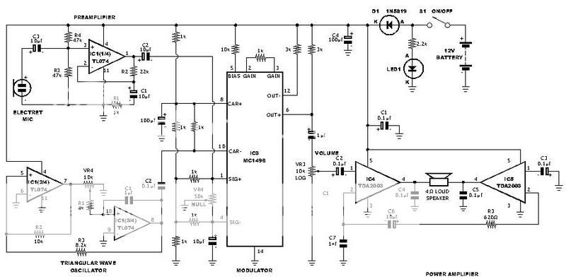
I dropped the XR2206, partly because it was too good for my application (although it would have given me the chance to try different waveforms), but the main reason was that some scallywag cleaned out my supplier's entire stock overnight!
I'm still working on using the MC1496 as, to be honest, I can't figure out the ins and outs of the other methods suggested (I'm still very much a novice). The pre-amp now uses a TL074 and I'm using two amps from the same IC to generate either a triangular or a sawtooth carrier. I need to do some testing to see which works best.
I also changed to the twin TDA2003 low-cost power amp straight off the manufacturer's data sheet. This still gives 18W output, which should be okay for my needs.
I think I understand the principal that phase_accurate was making about the 4066. I assumed the square wave was still a carrier, but now I think I understand it is used to switch something over in the 4066, giving a sound something akin to a modulator. I'll have to assume that the Vader Voice doesn't do this, which explains why it doesn't produce the right sound.
I know I haven't posted for a few days, but this is very much a "live" project for me, and something that has really piqued my interest. Thanks to everyone who has replied. Keep 'em coming!
Phil
the vader effect actually turns the audio on and off at a very high rate of speed. the dalek sound switches the phase of the signal from 0 degrees (noninverting) to 180 degrees (inverting) at a high rate of speed. there is still audio present at all times. using a 4066 to switch an op amp between inverting and noninverting would be the same effect as driving the Y input of the MC1496 with a square wave carrier.
- Status
- This old topic is closed. If you want to reopen this topic, contact a moderator using the "Report Post" button.
- Home
- Live Sound
- Instruments and Amps
- Ring Mod Design - comments welcomed!