definately the tranny
Well it took me a month in theory, (why is it so? etc) and 5 min in the shed to work it out.....
It's the transformer....when I subbed it with the fender princeton tx OMG !!! what a fantastic sounding amp.....so quiet too !!!
SSSSooooo whats going on with the other one ?...variable tapps 6K and 8K and 4 & 8 ohm sec resistances as stated above... 30htz / 40khtz....Fergusson,OT308 4/8
I think this is whats called hysteresis distortion (learn something new every day)..... but I could be wrong
I would like to thank everyone who commented with help , I do appreciate the wisdom of the many
Rifraf50
Well, congratulations!It's the transformer....when I subbed it with the fender princeton tx OMG !!!

Sometimes 5 minutes of experimenting trumps 5 months of theory, at other times it's exactly the opposite. Which is why we need both theory and experiment to keep us moving forward!
My guess is that it is internally damaged, perhaps with some internal shorting between adjacent copper turns. That might also explain any temperature-sensitive behaviour you saw, as the transformer internals expand or contract and move around slightly with temperature changes.SSSSooooo whats going on with the other one?
Normally you'd only run into excessive hysteresis if the manufacturer used really poor quality material to make the transformer laminations. (Hysteresis is a property of the core material.)I think this is whats called hysteresis distortion (learn something new every day)..... but I could be wrong
Plenty of DIY guitar amps have now been made using $5 audio line transformers for the output, and nobody seems to have been plagued with terrible distortion even from those cheap transformers...
-Gnobuddy
yes but !
Its a strange thing that it can run each tube independantly on either side of the winding yet with both tubes in it distorts uncontrollably.....the transformer itself never got hot at all and is quite large, nearly twice that of the Princeton 35 watt....its spec is 12watt rms conservative.....its only the second used vintage tranny iv'e used and thought this would be a good performer....probably why I struggled with it for a while....
Yes the M1120 is the perfect choice for a budding amp builder either as push pull or single ended.....just a tad short on natural bass.
Ive used them on 6aq5 pp , 6bq5 pp , and 6l6 class A .....notably the 6l6 class A is a great sounding amp...very pro sounding and would sound good as hifi as well....
Aha! A major, major clue!...it can run each tube independantly on either side of the winding yet with both tubes in it distorts uncontrollably....
What you are describing immediately points to a phasing problem, i.e., the start and end of one of the primary half-windings are scrambled. One half-winding is reversed, compared to the way it should correctly be connected.
Is it possible you have got the actual primary centre-tap mis-identified as one of the primary ends? That would cause the reversal problem.
A valve push-pull output stage is actually a sort of weird differential amplifier. We drive the two inputs with opposite phases, so the outputs are also in opposite phases. In a perfectly linear and perfectly matched world, adding these two anode currents together would cause the signal to cancel completely. But if we subtract them instead, we get the output we want.
Part of the output transformers job is to perform this subtraction of the two outputs (anode currents). If the primaries' centre-tap and one end are swapped, the transformer will instead attempt to add the two anode currents together. What happens then is that the linear part of the output signal (the Hi-Fi part) will partly cancel out, depending on how well matched the output components are. But the distorted parts (even harmonics, to be specific) will add rather than cancel.
I would expect the result to be low gain, and heavy distortion from the output stage.
Your earlier guess about saturation might also have been on the mark: if the OT primary centre-tap and one end are swapped, the DC magnetic fields from the two half-windings will not cancel, as they're supposed to. Instead they'll add inside the transformer core, pushing the core towards magnetic saturation.
Maybe your vintage transformer is fine after all, and you just happened to mis-identify the primary leads? (I hope you have your own notes or photos documenting the way you had it connected when it was mis-behaving, so you know how to fix it!)
-Gnobuddy
That certainly looks right, especially with the colour coding (single red wire). But, thanks to your parts-swapping exercise, we now know for a fact that something is wrong with the transformer as wired into your last circuit. Either the transformer is internally defective, or it was mis-wired. The question is, which?
So, if you have the energy, let's press on with the investigation! Maybe that transformer is a dud, maybe not - wouldn't it be great if we could find out that it is, in fact, okay?
Easiest starting point: have you measured the blue-to-blue resistance as well? If you haven't, please take a minute to do so. If red really is the center tap, then blue-blue resistance should be the sum of the two red-blue resistances, i.e., about 216 ohms in your case.
If you have access to a dual-trace oscilloscope, then all this becomes very simple. Disconnect the output transformer from all DC voltages, drive the speaker side of the OT with a small sine-wave signal (this could come from the 6.3 V AC heater winding with a 1W, 220 ohm or bigger power resistor in series to limit current). Then ground the red wire, and look at the phases of the two blue wire signals. They should be inverted.
If you don't have an oscilloscope, but do have a meter with an AC volts range, something similar (but less visually obvious) can be done. As before, drive the secondary (speaker side) with a small AC voltage, then measure AC voltage on the primary side between each two terminals: blue-red, blue-blue, and the other blue-red. If all is well, blue-blue should be twice the voltage you get from either blue-red connection.
One last thing: do you have a schematic for the original vintage circuit that this transformer came from? That would tell us how the original manufacturer wired the transformer.
-Gnobuddy
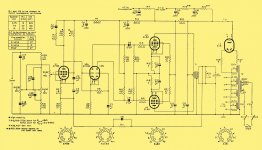
mullard 5-10 schem
Hi,here is the original schem....apparently these were built a lot by people such as us all over the world in the 50's......the chassis I have is made from brass plate.
the transformer is a OP308/8.4
http://www.kevinchant.com/uploads/7/1/0/8/7108231/ferguson_transformers.pdf
Funny thing....I just look at it , and it spec's the secondaries as 8.4,2.1 !!!!
I have misread this as 8 or 4 ohms but think now its 8.4 ohms (and 2.1 ohms )
What I have done is wire the 2 secondaries in series assuming they were 4 ohms each !!!....this means the output is currently 10.5 ohms !!!.....or 1 is out of phase maybe partially canceling the other phase out because of the imballance ?
Bit of a silly oversight perhaps...what do you think ?
Attachments
And more
ok....the secondaries are in 2 windings , 1 reads .63 ohms and the other reads .48 ohms.....depending how long you wait....
.63 = 8.4 ohm spkr winding ?
.48 = 2.1 ohm spkr winding
I can see I'm gonna have to run some volts thru and calculate to determine if I have to connect both to get the required match
Bugger.....already mounted the other !!!!
Do you know how hard it is to get a 6v battery and tap the wire on the terminals 50 times a second !!!!!
(I'm joking )
Sorry for the slow response, it's been a long hard day at work. Just got home, and it's after 8 pm here.Hi,here is the original schem...
Interesting schematic - Baxandall tone control first? Must have been designed to be driven from a low-impedance preamp.
I was hoping for output transformer wire colours on the schematic, but no such luck! (If it was a DIY design, that makes sense - people might have used any of several different transformers with it.)
Cool! Those were the days! Copper seems to be headed towards being un-obtanium; it's now so expensive that you see less and less of it, except where there is absolutely no alternative, such as in electrical wiring....the chassis I have is made from brass plate.
Okay, push-pull, 6k or 8k. Are there five wires on the primary, then? I would think there should be: 8k, 6k, centre-tap (B+), 6k, 8k.the transformer is a OP308/8.4
If there are five wires, and/or some are now missing, that would certainly introduce some possibilities for mis-wiring!
I looked through the transformer data sheet - amazingly, there doesn't seem to be a diagram showing wire colours, or the arrangement of lugs on the transformer. So we still don't have a easy way to be sure which primary wire is which! (Or did I miss something in that transformer catalog?)
Weird, isn't it? Designed for two 4.2 ohm speakers, which could be either wired in series, or in parallel?Funny thing....I just look at it , and it spec's the secondaries as 8.4,2.1 !!!!

It's certainly possible for the two secondaries to be in series anti-phase. But I don't think that shouldn't really cause the kind of distortion you were hearing - it will mis-match the valves to the speaker, sure, but that's not as bad as mis-matching one half of the push-pull stage to the other; having "push" not equal to "pull". (That's what would happen if the primary was mis-wired.)What I have done is wire the 2 secondaries in series assuming they were 4 ohms each !!!....this means the output is currently 10.5 ohms !!!.....or 1 is out of phase maybe partially canceling the other phase out because of the imbalance ?
-Gnobuddy
a diferent tangent
Because of the different ohms on the secondaries I was on another tangent....perhaps 1 winding was 8 ohms and the other 2 ohms......but I cant think of a reason why it would be made that way....it certainly makes more sense to make it with 2 x 4 ohm windings.....so why wouldnt they spec it as 2 x 4ohm instead of 8 / 2 ohm ......I know it means the same thing....but ?
curious and curioser.....
I have no idea why the transformer manufacturer would choose to make separate 8.4 and 2.1 ohm windings - at a guess, maybe for easy switching to suit then-available 8.4 ohm and 2.1 ohm speaker cabs?
So are there five wires on the transformer primary side? I would think there should be, with a centre tap and push-pull 8k and 6k windings.
-Gnobuddy
So are there five wires on the transformer primary side? I would think there should be, with a centre tap and push-pull 8k and 6k windings.
-Gnobuddy
4 wires
No...its as I said, 1 green 2 blue 1 red.....4 wires
green.............blue................... red...................blue
130r I________97rI___________B+___________I119r
........____________________________________
............. ____________.........____________
............. I-----.62-------I........I------.48------I
the secondary winds are slightly different.....2 independent winds 1 reads .62 the other .48
This would suggest the center would always be about 1k off center in regards to B+..... a - a would be right but voltage may vary a little ?
Might just use as a single ended thingy and give to someone.....its big enough to.
Oddball but so
Yeh its so , but I've given up trying to make it work.....the transformer is quite large for its power rating.......I was looking for an answer but it defies every solution I throw at it
Just cant see why it saturates the way it does , if that's what it is ?...like I said before its almost useable at 1/2 its wattage , but useless to me at that
Given its size it would make a good Class A / 6l6 .....yeh I know ..no air gap etc but it ran OK putting class A 6bq5 through half of it...
Strange thing the M1120 tx has no air gap but sounds (always gonna have difference of opinion on that) better as class A than AB to my ears anyhow and don't seem to saturate at full vol with a 6l6 given the physical size of it.
cheers
Last edited:
For an end to the transformer crisis I was able to buy one off flea bay, identical to the problem tranny I had.....turns out it had 1 red 2 blue and 2 green....(1 extra green)
So obviously prior to my knowledge and without being able to reference data on it in any way I have blundered and dragged everyone along with it....MY Apologies...
Obviously one green had been pulled from it in the past....why / how ?
It did make a nice single ended 6l6 guitar amp though which I sold on flea bay to help fund other projects.....
thanks for those who helped along the way and please excuse my idiocy....from time to time
Last edited:
If this is a guitar amp, then usually a little PI imbalance is desirable to help reduce cancellation of even order harmonics. However, as we can see here, something seems to be going quite wrong with this PI, far more than the state of its balance.Have you checked the wave form from the phase splitter? It is usual, as the ECC83/12AX7/12AU7/6SN7 etc are not balanced, gain wise, to adjust the anode load resistors accordingly. Pin 1 with 100k and pin 6 with 82k gets it somewhere near.
resolved
Yeh I discovered it was the output transformer....I was aware that there was imbalance in the long tail PI so I changed it to a cathodyne PI....the result was the same
as mentioned in the last post I discovered that a wire had been pulled from the transformer itself but me not knowing and with no data available assumed it was a transformer with variable taps...in this case 6K and 8K however this transformer only had 4 wires and the red did not show itself to be centred to any of them....
so I had resistances of 97ohms,blue , 130ohms,green and 119ohms blue (cant quite remember)
this made me think that red was B+ and the 6 & 8k was the 97 or 130 ohm as they were on the same wire 119ohms was on its own
The only data I had was catalogue entry which described it as a transformer made for the 5-10 Mullard monoblock which stated impedence and wattage but nothing else (not how many wires and what colour etc)
I was able to purchase one a short while back as a NOS item and guess what ? 2 green 2 blue and 1 red...which can only mean that I wire has been pulled out of the transformer.....yet oddly enough the windings were not very well centered around the B+.......I can only think that the external radii created a longer wire to the same number of windings in the internal windings and hence more ohm's
So in conclusion I was connecting 7k to the output tubes but with 4k and 3k each side of centre......would this cause the transformer to saturate ?
perhaps if I had used the 6k circuit blue/blue it may have worked but after I subbed it with another tranny I just left it as it was and the fate of the dud became a tranny to a 6l6 SE unit which worked quite nicely.
Thanx good folk of DIY
Well, that finally solves that mystery!it had 1 red 2 blue and 2 green....(1 extra green)
No worries, that's normal operating procedure in the world of DIY, I'd say.I have blundered and dragged everyone along...
And these long-distance diagnostic exercises are like fire drills, in a way: they help keep our skills honed, which is no bad thing!
-Gnobuddy
That OT308/8.4
It has 2 off 2.1 Ohm secondary windings.
Put them in parallel for 2.1 Ohms output impedance.
Put them in series for 8.4 Ohms output impedance.
Getting phase correct is essential.
I have a OT308/15 on my shelf. It has 2 off 4 Ohm secondary windings, parallel connect for 4 Ohms and series connect for 15 Ohms.
Cheers,
Ian
- Status
- This old topic is closed. If you want to reopen this topic, contact a moderator using the "Report Post" button.
- Home
- Live Sound
- Instruments and Amps
- Phase inverter distortion