Take a look: REDactives Active Pickup SystemFor that reason, I've been strongly considering building a tiny pre-amp board to be installed inside various guitars, specifically to offer as near to "no load" as i9s possible with the best in modern op-amps, and thus offering the player a situation where his/her guitar is going to sound its brightest into any load.
There are also active pickups, with integrated amplification. They are usually sold for more distorted musical styles, and have been around since at least the 1980s.
More recently, there are the Fishman Fluence pickups. A super-low-inductance printed-circuit coil substitutes for a traditionally wound coil, and the onboard preamp brings up the signal level - and equalizes it - to match conventional guitar pickups.
I'm unsure about the use of the word "better" here. I would agree that this is the route to a wider and more predictable frequency response, though.I think we are all keenly aware that the closer you can get to a no-load situation, the better your high end response.
When it comes to guitar amplification, a wide bandwidth is not necessarily a good thing, especially with more heavily distorted types of guitar music. A wider bandwidth may actually be very unpleasant in some cases.
Agreed. A way to objectively characterize (measure) the difference is what I'm interested in, too.But being able to determine that, at least approximately on a bench without having to physically install is something that I'd find super valuable.
-Gnobuddy
I built my own electric guitar in my twenties, poverty being the mother of invention. Like you, I didn't know what I was doing, and wound a few thousand turns of 42 gauge wire onto home-made plastic bobbins....I rewound a bobbin over an alnico bar magnet with relatively heavy wire then used a cheap tiny mic matching transformer - it was quite "hi-fi" compared to say a regular stock P-bass pickup. I had no way to measure inductance and really didn't know what I was doing at the time - but it worked.
I ended up with pickups that measured about 4 kilo ohms DC resistance. I thought that was a lot, but it turns out that's about half of what is typical for commercial products.
My pickups had the same characteristic you described - wide, neutral-sounding, "Hi-Fi". Rather sterile-sounding for electric guitar, IMO, but would have been well suited to amplifying a steel-string acoustic guitar.
I am sorry to hear it. The loss of the ability to makes one's own music is a deep one.My fingers have recently become "numb" so no guitar fun anymore.
I myself am experiencing some of the earlier symptoms of osteo-arthritis in my hands, and I dread their worsening to the point where I can't play guitar any more.
-Gnobuddy
I agree with gnobuddy, but want to add you have to consider the speaker as part of the audio chain. A typical guitar speaker peaks at about 2.5 khz, above that drops rapidly. So if you guitar pickup peak at a higher frequency, the resulting frequency response of the hole audio chain may be extended above this 2.5 kHz peak to perhaps 4kHz, and maybe that is what les Paul intended.
Boosting 6kHz in a linear sound system is just another story...
Boosting 6kHz in a linear sound system is just another story...
Reading that was a deja-vu moment. I must have read it before, and forgotten about it.By the way Gnobuddy, I found this interesting article that shows a pickup tester, that seems to work a lot like what you suggested.
Yes, high-frequency core losses almost certainly play a role in the pickup sound. This is the only logical reason I can think of for the supposedly different sounds of Alnico and ferrite magnets in guitar pickups. (Alnico has much higher electrical conductivity, and therefore much higher eddy current loss at high frequencies.)...one thing i did wrong, was I used a pickup bobbin with a steel insert core.
I think the choice of high-output, high-impedance pickups was driven by the high cost of valves way back in the 1940's, and by the limited technical knowledge of the electric guitar pioneers. The failings of this approach are apparent, with generations of single-coil players having to put up with hum, buzz, and other unpleasant electrical interference....so i won't pick up so much noise from all the 1 Meg HIGH-Z input.
In the 1970s Alembic built bass guitars with relatively low impedance pickups, onboard preamps, and active filters to generate desired (and adjustable) frequency responses.
Bass players tend to be willing to embrace new technology, but electric guitarists do not; they tend to want to play more or less exactly the same thing Jimi played five decades ago. Many failed attempts at guitar innovation have come and gone, because guitarists wouldn't change their preferences (or their vintage equipment).
It will be interesting to see if the Fluence pickups gain any traction. I have a feeling not too many guitar collectors will ever consider installing them in, say, their precious vintage Fenders and Gibsons.
-Gnobuddy
Take a look: REDactives Active Pickup System
There are also active pickups, with integrated amplification. They are usually sold for more distorted musical styles, and have been around since at least the 1980s.
-Gnobuddy
As we're both obviously in agreement about poverty being the mother of invention, i'm sure you can understand my philosophy here when I say this: If I have a simple idea that works, its usually not an innovation or anything patentable. So when i examine what others successfully doing it have done, and examine their prices, I quickly conclude that for the cost of buying ONE of "theirs", I can probably build a dozen, including cutting PCBs (thanks to cheap China boardhouses). then i get to build it exactly as I want it, ready to install on any guitar, and after i do my own can add a new product to my own inventory. It may or may not sell, but I'm always happier knowing I made my own and did it exactly as I wanted.
In this case, I'll be making a single small board that can handle up to 3 pickups, offer active tone controls and mixing for each, or allow combined pickup tone control. This way, you can add it to any guitar and from then on, guitar cords don't matter. And if the buffering allows wider bandwidth, one thing is apparent from all these write ups on pickups: Its VERY easy to drop the bandwidth and move the pickup "peak" lower. But if its already low, you can't do the opposite.
Last edited:
I agree with gnobuddy, but want to add you have to consider the speaker as part of the audio chain. A typical guitar speaker peaks at about 2.5 khz, above that drops rapidly. So if you guitar pickup peak at a higher frequency, the resulting frequency response of the hole audio chain may be extended above this 2.5 kHz peak to perhaps 4kHz, and maybe that is what les Paul intended.
Boosting 6kHz in a linear sound system is just another story...
Absolutely! In fact in my current project ( my reason for this whole original post), I'm seriously considering the use of opf a tweeter. I know that doesn't make sense as I've not explained my whole project here. But I will point out that unlike a lot of guitarists, I've become very attached to the sound of my electric guitar through a PA, after the effects pedals. Part of that is because when I do want to go clean, the tweeters and horns can't be beat for helping to squeeze out something closer to an acoustic sound. Later, for a mellow overdrive, its easy to cut back on the the treble.
Copyrighted material removed.
Wondering about that, sorry. Was going to just post the link but as I said going to the page was an invitation to get attacked by a virus. Shame the other links are also gone though, looked like some things to get people pointed in the right direction.
Ah, now I have a better idea what you're after. Thanks for the clarification!I simply wanted a way of predicting which pickups would do better in the only area I found SOME to be lacking... and that is high end.
For a wide response and a tall resonant peak, clearly the electrical requirements are (a) low inductance and self-capacitance, and (b) low iron losses at high frequencies.
I only have limited experience with pickups, but from what little I have, reducing the number of winds in the coil is the easiest and most consistent way to get what you're looking for - crisp, clean, extended treble (and reduced copper losses).
So it seems that the ideal starting point for you is cheap pickups that have skimped on the cost of copper wire (by reducing the winds in the coil). Cheap ferrite magnets are also almost certainly an improvement over (more expensive) Alnico, as they will have reduced eddy current losses, and extended high frequency response.
If the pickups you're sourcing from Ebay list a winding resistance, that is probably your best guide - get the ones with the lowest winding resistance.
As for a suitable measurement technique, why not measure the DC resistance and self-inductance of the pickup winding, and just use that data? That should be enough to quickly narrow down your choice of available pickups. You may not need an accurate way to measure the pickups entire frequency response.
-Gnobuddy
Ah, now I have a better idea what you're after. Thanks for the clarification!
For a wide response and a tall resonant peak, clearly the electrical requirements are (a) low inductance and self-capacitance, and (b) low iron losses at high frequencies.
I only have limited experience with pickups, but from what little I have, reducing the number of winds in the coil is the easiest and most consistent way to get what you're looking for - crisp, clean, extended treble (and reduced copper losses).
So it seems that the ideal starting point for you is cheap pickups that have skimped on the cost of copper wire (by reducing the winds in the coil). Cheap ferrite magnets are also almost certainly an improvement over (more expensive) Alnico, as they will have reduced eddy current losses, and extended high frequency response.
If the pickups you're sourcing from Ebay list a winding resistance, that is probably your best guide - get the ones with the lowest winding resistance.
As for a suitable measurement technique, why not measure the DC resistance and self-inductance of the pickup winding, and just use that data? That should be enough to quickly narrow down your choice of available pickups. You may not need an accurate way to measure the pickups entire frequency response.
-Gnobuddy
First, I came to realize early in this discussion that the instruments I have for measuring inductance do not work with pickup coils. Someone else independently pointed out that it was problematic too. I also observe that inductance measurement likely won't show anything about magnet strength or quality. Second, among the few pickups I have here, I have found the exact opposite of what you say to be true. That is, the pickup with the best treble response (both audibly and when tested via the test setup with the two 1meg resistor using the ARTA tool) was the one whose DC resistance was higher.
So no offense to you or anyone, because this has all been helpful. But what I can not do is ignore actual data I've seen so far.
How about applying a constant (AC) voltage, and using a small series sense resistor to measure current at two frequencies? Assuming a series LR circuit, it should be possible to calculate L from that.First, I came to realize early in this discussion that the instruments I have for measuring inductance do not work with pickup coils.
Another possibility: an old-fashioned (but very effective) bridge measurement. Some thought is needed as to the best way to balance a bridge with a lossy inductor (pickup) in one position.
True, but magnet strength only affects the strength of the output signal, not it's frequency response.I also observe that inductance measurement likely won't show anything about magnet strength or quality.
Iron losses certainly do have an effect. Thanks to the small pole-pieces and low bandwidth, I suspect the only place where there are substantial iron losses is the big bar magnet used in humbuckers. There, ferrite vs Alnico does seem to make a difference.
While possible in theory, I have yet to see iron losses so heavy that they swamped out the effect of a lower inductance winding.
The pickup intended to amplify acoustic guitar had a higher coil resistance than the pickup intended for electric guitar duties? That is not the usual state of affairs....the pickup with the best treble response (both audibly and when tested via the test setup with the two 1meg resistor using the ARTA tool) was the one whose DC resistance was higher.
Two (improbable) possibilities come to mind:
- Is there a possibility that there is a series resistor encapsulated in the high DCR pickup?
- Could the high DCR pickup have been wound with fewer turns of thinner wire, thus having lower inductance?
I would never advocate ignoring trustworthy data. That route leads straight to superstition and nonsense. Before you know it, you'll be sacrificing Alnico magnets to the pickup Gods, and claiming your best-sounding pickups were manufactured during lunar eclipses....what I can not do is ignore actual data I've seen so far.
-Gnobuddy
I agree with gnobuddy, but want to add you have to consider the speaker as part of the audio chain. A typical guitar speaker peaks at about 2.5 khz, above that drops rapidly. So if you guitar pickup peak at a higher frequency, the resulting frequency response of the hole audio chain may be extended above this 2.5 kHz peak to perhaps 4kHz, and maybe that is what les Paul intended.
Boosting 6kHz in a linear sound system is just another story...
I'm glad you reminded me of this, because it seems to be one of the most important points for me which I have been ignoring. I have mostly been listening through some so-called "full range" speakers, which might be sufficient if I were simply after a "typical" electric guitar tonal range. But the fact is I'm using a magnetic pickup in a small acoustic guitar, and have been hoping to hear higher harmonics then I'd usually care about.
After i read your post, I switched to a better speaker that incorporated a tweeter. I'm certainly still hearing that one pickup does better then the other on the high end. But I'm also hearing that even my original (VERY cheap) pickup is behaving more acceptably, with just a little crank of the treble control. This is undoubtedly because I have the unusual advantage of a high-Z buffer preamp. Based on all our discussions, particularly about loading, this is likely the key to getting the most out of low cost pickups. But as you've pointed out, the speaker system makes a huge difference. The difference is literally what you'd expect putting new strings on a guitar who's strings have gone dead.
How about applying a constant (AC) voltage, and using a small series sense resistor to measure current at two frequencies? Assuming a series LR circuit, it should be possible to calculate L from that.
Another possibility: an old-fashioned (but very effective) bridge measurement. Some thought is needed as to the best way to balance a bridge with a lossy inductor (pickup) in one position.
-Gnobuddy
Yes... I absolutely must do this, AND more, I really should purchase a good fluke L/C meter that can better evaluate larger inductances like this. In any case, a simple bridge circuit, once properly set up, would indeed allow me to at least measure both resistance and inductance.
True, but magnet strength only affects the strength of the output signal, not it's frequency response.
-Gnobuddy
That seems right, but then its hard to conclude when you read all you can on this online. Like you say, some is "pseudo science".
The pickup intended to amplify acoustic guitar had a higher coil resistance than the pickup intended for electric guitar duties? That is not the usual state of affairs.
Two (improbable) possibilities come to mind:
-Gnobuddy
- Is there a possibility that there is a series resistor encapsulated in the high DCR pickup?
- Could the high DCR pickup have been wound with fewer turns of thinner wire, thus having lower inductance?
I've had it apart, and no there is no series resistance. It DOES have a complete metal shell though... not on top bot all along the bottom and sides. I do believe metal shells go a long way to flattening out the usual peak you see in a pickup, though I didn't see a hugely different response shape so far (just a higher frequency peak).
I would never advocate ignoring trustworthy data. That route leads straight to superstition and nonsense. Before you know it, you'll be sacrificing Alnico magnets to the pickup Gods, and claiming your best-sounding pickups were manufactured during lunar eclipses.
-Gnobuddy
Unfortunately I only have a limited number of pickups (at least different ones), so my "sample" size isn't enough to rule out an unusual fluke.
Take note of my other answer to VoltWide about his speake suggestion. I can't believe I've neglected this for such a long time, especially considering my original complaint about my "cheap" pickup was based on what I was HEARING. There's still no question that one pickup has more high end, but suddenly I'm realizing that the difference may be manageable... at least as long as I stick with buffering my pickups, with the buffer right in the guitar (to avoid cable loading).
Lots of nonsense out there, but easy to ignore if you stick with the hard-won knowledge we inherited from some of the cleverest minds in human history....its hard to conclude when you read all you can on this online. Like you say, some is "pseudo science".
James Clerk Maxwell published his famous equations in the mid 1800s, and a hundred and fifty years later, we still haven't found a single classical electromagnetic problem that isn't successfully described by those same equations (except for a few exotic things that involve quantum behaviour.)
Guitar pickups are pretty simple devices in the scheme of things, really just a big coil of wire with a magnetic core. No quantum mechanics necessary...just Maxwell's dusty, 150-year-old equations.
I know you may have resolved your problem (by the addition of the tweeter), but now you've got my mind going on this business of what exactly guitar pickups do, and how we might measure what they're doing.
As a first step, I thought it would be interesting to do a few more LTSpice simulations. I was right, a few minutes with LTSpice was enough to have my head spinning with new thoughts.
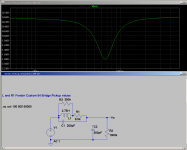
Take a look at the attached screenshot. In this simulation, the guitar pickup is loaded only by a 1 meg-ohm resistive load. (Note the 300 pF cable capacitance is disconnected).
Here is the surprise I wasn't anticipating: at the pickup's resonant frequency of roughly 6.5 kHz, there is a dip in the output. Not a peak.
But it makes complete physical sense: we know the impedance of a series LC network like this one is maximum at its resonant frequency. With the source impedance at its maximum, less voltage is delivered to the load. Hence, there is a (slight) dip in the pickups output signal at the resonant frequency.
There is more to come, in my next post or two.
-Gnobuddy
Attachments
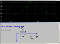
My next question was, what happens to this simple pickup model when subjected to Voltwide's measurement technique, i.e., driving it with an AC current coming from a 1 megohm source resistance.
The screenshot shows the answer. The impedance peaks at the resonance frequency, around 6.5 kHz. No surprises there. This simple electromagnetic model of a pickup reproduces the essential features of the constant-current-drive measurements made on actual pickups, and described in this thread by Voltwide and Peter Pan.
One more post coming up, to finish off my findings...
-Gnobuddy
Attachments
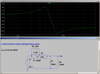
Finally, I added a cable capacitance of 300 pF, in parallel with the 1M resistive load. This is roughly equivalent to a ten-foot / 3 metre guitar cable with 30 pF/foot (100 pF/metre), which seems fairly typical.
And the addition of the parallel capacitance changes everything - not only is there a new resonant frequency at about 4 kHz, but it is accompanied by a +4 dB peak in the frequency response.
There are still traces of the original pickup resonance to be seen - there is still a dip in the pickup's output signal, at around 7.5 kHz this time. It's moved up a little bit in frequency - typical behaviour when you couple two resonances.
For me, things have become both clearer, and, paradoxically, more confusing. I'm pretty sure that the audible differences we hear between pickups is not caused by a subtle 2 dB dip at 6 or 7 kHz, so these results strengthen my belief that the resonance with the cable capacitance is the one that matters (in a passive guitar, no onboard buffer).
But what do we make of the guitar pickup fed straight into a 1M resistive load? There is no peak at all in the response, just a dip instead?
Well, in practice, even a buffer amp has some input capacitance. So I experimented with varying amounts of parallel capacitance.
30 pF wasn't enough to change the results much - still no peak, just a big dip at 7 kHz.
Going up to 100 pF of parallel capacitance was enough to produce a small (1.5 dB) peak at 4.5 kHz.
Based on what I'm seeing in these simulations, I think that some amount of capacitive loading on the pickup is a good thing.
I'm sure that a simple electrical model like this cannot incorporate all the physical subtleties of an actual guitar pickup. But I think we may have enough here to get a good understanding on the basics of how these deceptively simple devices work.
-Gnobuddy
Attachments
That, of course, should have been "parallel", not series. My apologies for the momentary slippage of the mental cogs....we know the impedance of a series LC network like this one is maximum at its resonant frequency.
-Gnobuddy
Here is the surprise I wasn't anticipating: at the pickup's resonant frequency of roughly 6.5 kHz, there is a dip in the output. Not a peak.
-Gnobuddy
Makes sense. So that's all the more reason to push the resonance point as high as possible, to make it matter the least. As I've said, you can always remove what you don't want with EQ, but doing the opposite is often impossible. Considering how small and low power buffer amplifiers can be made, and how many guitarists complain about the cost of quality cables, you'd think EVERY guitar would include at least a single output buffer, if not a buffer for every coil. Since it would have to have a switch to turn it off, that could also serve as a bypass for the "purists".
Oh and just so you know (as is often the case), adding the tweeter solved one problem but created another. Such is the nature of developing!
")
Thanks for the comments! Any chance of a link to some more info on this?...most modellers put the pickup capacitance and any extra damping loading to ground rather than just across the passive coil and resistor element.
I am confused by your comment, because we know there is stray capacitance between every two nearby wires in a coil. Lumping all of that into one capacitance is a simplified approximation. But surely, the physical reality is that this lumped capacitance appears across the ends of the coil, i.e., in parallel with the inductance.
There are electrical network theorems that let you convert series impedances (including capacitive ones) to equivalent parallel ones (Thevenin and Norton equivalent circuits). But the two circuits behave identically - that's why they're "equivalent" circuits. So, using this approach to switch a parallel capacitance to a series one will not change the modeled frequency response.
So, any link to information on alternative ways of modeling a pickup would be welcome. I'd like to find out what, if anything, I'm missing.
-Gnobuddy
Sure thing!
This link from Helmuth Lemme seems to be the one most referred to on this subject:
BuildYourGuitar.com :: The Secrets of Electric Guitar Pickups
Take a look at Fig 2 there, to see the cap going to ground. I had the same thoughts as you about the capacitance being inherent in the coil and how each turn is really its own element and how we are representing it all as a 'lumped' single model. But I think Lemme is right here, because each coil turn, with its bit of R, L and C, also has its own inherent signal generation, and the cap element has to go around that too. The cap needs to be able to shunt some of the signal from the source.
If not, imagine a case where we had the pickup represented by a model, feeding into a very high impedance input. The RLC network, being all in series with the source, would then be all negligible and we would just get a flat voltage output. In practice, the unloaded pickup has its own high resonant frequency.
So, a typical pickup can be represented in the first instance, by RLC as shown by Lemme, and there is a link in his paper to some values. eg, a PAF type might be 3.8H, 7k and 130pF, a low-wind Strat single 2.2H, 5.4k and 80pF etc.
You can put those in a SPICE model, and then add pots, tone cap, cable cap amp load etc and get some very useful results to help inform choices about components in the guitar eg pot values, treble bleed networks etc.
My interest in all of this is to make a spreadsheet that tries to capture all of that in a simple interactive form. I've been picking away at this for several years, my spreadsheet is called GuitarFreak and it can be googled and downloaded via Guitarnuts2.
Going back to the modelling, once that SPICE model is set up (or spreadsheet), as useful as it is, it is apparent that the results still look nothing like an actual frequency response recorded from a real guitar, even setting aside any variation due to the amp. There are several extra effects that apply, which include pickup position, fretting position, plucking position, the relative magnitude of string harmonics, the sensing width of pickups, body resonances and damping.
But the good news is that most of these effects can be understood with a bit of physics and maths. So I put them into my models, using references by Jungman and Tillman.
Recently, through the link on Stratalk that I posted here before, the issues of pickup damping have become slightly clearer. Now setting aside all the extra physical effects and looking again just at pure electrical response, there are still significant deviations between tested pickups and the peak responses from the simple three part Lemme models. Lemme illustrates some of it at Fig5 in his paper, but there are eddy currents happening in metal components such as poles, base plates and covers that damp the peaks significantly and contribute to tone.
This extra damping has a small but significant effect on say, a nice simple alinico single coil, and a massive effect on those with more conductive metals involved such as steel poles and covers.
Testing
The guys testing this are feeding a uniform voltage signal sweep, via a resistor into a low-wind exciter coil placed over the pickup. The resistor is chosen to have much higher impedance than the coil, so taking out any effects of the coil reactance and resulting in constant current. This results in a consistent flux generation, with an output induced in the pickup which rises at a constant 20db per decade (approx 6db per octave). This is because induction is dependent not on flux but on rate of change of flux.
So they have designed and both built, an integrator to take out that 6db slope. This takes the signal out of the pickup being tested, and brings it back to a nominal flat gradient plus peaks (like we model in Spice)
Modelling
This is where I get interested, to try to capture the resulting electrical response in an improved electrical model, to then combine with all the other effects. I'm getting very good results with not a 3-part model but a 6-part model of the pickup. It has two extra loading branches, one is resistive and one is a resistor and inductor.
Here is an example, from tests on a Seymour Duncan SSL-1. The dashed lines are the results traced from physical tests either direct to a high-impedance scope, or loaded by 200k and 470pF to represent a guitar load. the solid lines are calculated from a 6-part model.

Here is a screen shot of the front page of GuitarFreak (this version in development, not uploaded yet):

It represents a 6.2k Texas Special. the blue line represents just the electrical response, within a guitar, using the six part model. See the top left green zone to see how the model is arranged and the values being used.
The green line is the same Texas special but modelled with just three parts, no extra damping - see how it peaks a bit higher.
The red line then takes that and adds the pickup/string/harmonic effects - as if strumming across all strings. You can see the frequencies of the lower strings and their harmonics. There are other options to plot a smoother envelope of all that.
How 'accurate' is that? I make no claims there! strumming a guitar is obviously a very variable activity, and there are several effects still not represented. But, its getting better. This last plot takes that Tx Special, which is actual representative of my own Strat. Here it is superimposed on an actual recorded trace (into a neutral buffer):

I don't know how that looks to others, but I was pleased with how the calculated and tested traces follow similar profiles.
(Note: the recorded trace captures every harmonic at its own frequency, the spreadsheet only calculates at 12 points per octave and each harmonic (30 per string) is shifted to the nearest interval - hence it appears less fine grained than the recorded trace)
What do you think?
This link from Helmuth Lemme seems to be the one most referred to on this subject:
BuildYourGuitar.com :: The Secrets of Electric Guitar Pickups
Take a look at Fig 2 there, to see the cap going to ground. I had the same thoughts as you about the capacitance being inherent in the coil and how each turn is really its own element and how we are representing it all as a 'lumped' single model. But I think Lemme is right here, because each coil turn, with its bit of R, L and C, also has its own inherent signal generation, and the cap element has to go around that too. The cap needs to be able to shunt some of the signal from the source.
If not, imagine a case where we had the pickup represented by a model, feeding into a very high impedance input. The RLC network, being all in series with the source, would then be all negligible and we would just get a flat voltage output. In practice, the unloaded pickup has its own high resonant frequency.
So, a typical pickup can be represented in the first instance, by RLC as shown by Lemme, and there is a link in his paper to some values. eg, a PAF type might be 3.8H, 7k and 130pF, a low-wind Strat single 2.2H, 5.4k and 80pF etc.
You can put those in a SPICE model, and then add pots, tone cap, cable cap amp load etc and get some very useful results to help inform choices about components in the guitar eg pot values, treble bleed networks etc.
My interest in all of this is to make a spreadsheet that tries to capture all of that in a simple interactive form. I've been picking away at this for several years, my spreadsheet is called GuitarFreak and it can be googled and downloaded via Guitarnuts2.
Going back to the modelling, once that SPICE model is set up (or spreadsheet), as useful as it is, it is apparent that the results still look nothing like an actual frequency response recorded from a real guitar, even setting aside any variation due to the amp. There are several extra effects that apply, which include pickup position, fretting position, plucking position, the relative magnitude of string harmonics, the sensing width of pickups, body resonances and damping.
But the good news is that most of these effects can be understood with a bit of physics and maths. So I put them into my models, using references by Jungman and Tillman.
Recently, through the link on Stratalk that I posted here before, the issues of pickup damping have become slightly clearer. Now setting aside all the extra physical effects and looking again just at pure electrical response, there are still significant deviations between tested pickups and the peak responses from the simple three part Lemme models. Lemme illustrates some of it at Fig5 in his paper, but there are eddy currents happening in metal components such as poles, base plates and covers that damp the peaks significantly and contribute to tone.
This extra damping has a small but significant effect on say, a nice simple alinico single coil, and a massive effect on those with more conductive metals involved such as steel poles and covers.
Testing
The guys testing this are feeding a uniform voltage signal sweep, via a resistor into a low-wind exciter coil placed over the pickup. The resistor is chosen to have much higher impedance than the coil, so taking out any effects of the coil reactance and resulting in constant current. This results in a consistent flux generation, with an output induced in the pickup which rises at a constant 20db per decade (approx 6db per octave). This is because induction is dependent not on flux but on rate of change of flux.
So they have designed and both built, an integrator to take out that 6db slope. This takes the signal out of the pickup being tested, and brings it back to a nominal flat gradient plus peaks (like we model in Spice)
Modelling
This is where I get interested, to try to capture the resulting electrical response in an improved electrical model, to then combine with all the other effects. I'm getting very good results with not a 3-part model but a 6-part model of the pickup. It has two extra loading branches, one is resistive and one is a resistor and inductor.
Here is an example, from tests on a Seymour Duncan SSL-1. The dashed lines are the results traced from physical tests either direct to a high-impedance scope, or loaded by 200k and 470pF to represent a guitar load. the solid lines are calculated from a 6-part model.
Here is a screen shot of the front page of GuitarFreak (this version in development, not uploaded yet):
It represents a 6.2k Texas Special. the blue line represents just the electrical response, within a guitar, using the six part model. See the top left green zone to see how the model is arranged and the values being used.
The green line is the same Texas special but modelled with just three parts, no extra damping - see how it peaks a bit higher.
The red line then takes that and adds the pickup/string/harmonic effects - as if strumming across all strings. You can see the frequencies of the lower strings and their harmonics. There are other options to plot a smoother envelope of all that.
How 'accurate' is that? I make no claims there! strumming a guitar is obviously a very variable activity, and there are several effects still not represented. But, its getting better. This last plot takes that Tx Special, which is actual representative of my own Strat. Here it is superimposed on an actual recorded trace (into a neutral buffer):
I don't know how that looks to others, but I was pleased with how the calculated and tested traces follow similar profiles.
(Note: the recorded trace captures every harmonic at its own frequency, the spreadsheet only calculates at 12 points per octave and each harmonic (30 per string) is shifted to the nearest interval - hence it appears less fine grained than the recorded trace)
What do you think?
- Status
- This old topic is closed. If you want to reopen this topic, contact a moderator using the "Report Post" button.
- Home
- Live Sound
- Instruments and Amps
- Predicting high frequency cutoff of low cost guitar pickups