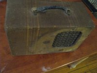
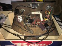
This amp rescue project is based on an EBay find that I think was a steal, but I still can not identify what it originally was. This was a small tweed case holding an 8 inch Rola field coil speaker and an amp utilizing a 6L6 power tube and a 6C8 preamp tube. Aside from the makers mark on the speaker, there was no other badge to signify the brand of this amp. Judging from the field coil speaker, the style of the capacitors and resistors, absence of any disc caps, and the 6C8 tube, I am estimating that this is 1940s construction. It was unmodified inside, except for an auxiliary input wire that was run in to the input jack – this also looked ancient. The winning bid for this was $27.00, I don’t think I had any competition for this. There were a lot of unknowns in this purchase, and the seller claimed only that the tubes did not glow when plugged in. Ever the optimist.
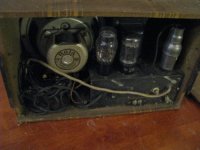
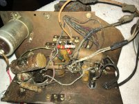
On arrival, the 5Y4 rectifier had an open filament. The 6L6 GB and the 6C8G tested well. The output transformer, voice coil, and field coil had reasonable resistance readings. All of the wiring except that of the power transformer had cracking insulation, and so I did not try to bring it up on a variac. This was going to be a complete rebuild, for safety and sanity.
The usual wiring of a field coil speaker places the field coil as a choke in the first pi filter of the power supply. Internet lore states that this arrangement adds the dynamic effect of boosting field coil current during hard playing – but this would apply to a push-pull amp only, if it is true. My field coil advertises 2000 ohms on its label, and tested at 1800 ohms. Encouraging.
The field coil speaker had numerous tears in its paper cone, and which seemed to be degraded from age and very brittle to the touch. The voice coil was scratchy, there was no end cap, and cleaning the gap with tape yielded rusty debris. I did clean it out enough to reduce the scratchiness, and repaired the paper cone with modpodge glue and black tissue paper.
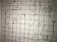
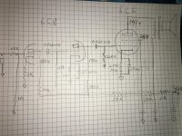
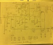
Basing the amp loosely on a Fender Champ 5E1, the following schematic was utilized. Surprisingly, this all actually worked somewhat. The transformer is large, quiet, and cool in operation, putting out 410 volts at the rectifier tube. The anode voltages with this arrangement were 300 volts at the 6L6 and 150 for each anode of the 6C8. The voltage drop across the field coil was 100 volts, in the right ballpark, based on internet lore of field coil speakers. I left the volume control out of the schematic, I see, but it is a 1 meg pot just before the 6L6.
This amp, still sitting on a bench actually worked and had a promising amount of power and very interesting tone. The biggest issue was that the speaker coil definitely still had a rub. This was evident only with low notes, the A and low E string, which brought the speaker to the end of its excursion. A closer look revealed that the spider was broken in two places. This type of spider is made of a fiber material which was fairly brittle.
I believe that a rebuilding of this speaker is possible, probably by some readers of this post. For the present, I wanted to forge ahead with the project. So, I set aside the field coil speaker. I obtained an 8-inch Rola alnico speaker, with a fairly generous magnet size, and substituted that. The field coil had been a part of the first pi filter, but a 1 K 5 watt resistor was substituted. Very good sound! I will probably upgrade to a 10 watt resistor once I’m settled on the circuit.
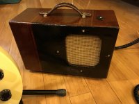
What about the tweed case? It was in very bad shape, dirty of course, and with a discolored area around the speaker. This looked like water damage, but on closer inspection may have been where a prior owner used bleach to clean the tweed. The cloth fibers were very degraded and peeling in this area.
A good cleaning helped the tweed, using Oxi-Clean fabric spray, Oxi-Clean car upholstery cleaner, a Mr. Clean dirt eraser, and naphtha, a lot of dirt came out. Amber shellac spruced up most of the case very well, but the discolored area only looked worse. Hiding this sad area was accomplished by making an opaque dark shellac and creating a rectangular two-tone panel on the front of the amp, with a more intentional look. I think the result was favorable. A new leather handle was added, as it was now looking like a worthwhile amp project.
My goal sonically was to go for maximum clean headroom, with mild crunch available with playing dynamics. I like to have the amp volume cranked, and control volume and tone at the guitar. I tend to have guitar volume at 5 – 6, and push it up as high as 10 when I want some distortion. My goal for this amp was to have a clean preamp, and generate crunch within the 6L6. Not very Champ-like, but I wanted something a little different.
To this end, a little more tweaking of resistor values was done from the original schematic. I did not add a bypass cap to the cathode resistor of the first triode, not wanting to overdrive the second triode. Two oscilloscope tracings are shown. The first shows the onset of visible distortion at the 6L6 output tube, the green trace. The smaller sine wave is the output of the preamp tube. This is shown in greater detail in the second tracing.
No doubt there will be further tweaking. I do not have an output measurement in watts, but it is a fairly loud amp. The voicing does not waste much power on bass, with the 0.022 coupling caps. I think this places my guitar sound where I want it to be in the mix, and makes the most of a small wattage amp.
It sounds really good, very expressive and revealing of the guitar’s natural sound. It seems to pair well with a Les Paul and an SG. With these, it is clean at a guitar volume of 5 and nicely crunchy at 10. It also sounds very good with a lap steel guitar with a horseshoe pickup, again letting the natural guitar sound through.
Possibly I will post some sound samples.
I would like feedback from any forum members on any of this, of course. This is my second guitar amp, so I welcome the suggestions and experience of others. In particular, I wonder:
1. Does anyone have experience or suggestions on the 6C8 preamp tube?
2. Does anyone have any idea what brand this ancient amplifier was, or anything else about it? Any guesses about it’s age based on what you see?
3. Any preferences in Champ variations, regarding output tubes, preamp tubes, output transformers?
On arrival, the 5Y4 rectifier had an open filament. The 6L6 GB and the 6C8G tested well. The output transformer, voice coil, and field coil had reasonable resistance readings. All of the wiring except that of the power transformer had cracking insulation, and so I did not try to bring it up on a variac. This was going to be a complete rebuild, for safety and sanity.
The usual wiring of a field coil speaker places the field coil as a choke in the first pi filter of the power supply. Internet lore states that this arrangement adds the dynamic effect of boosting field coil current during hard playing – but this would apply to a push-pull amp only, if it is true. My field coil advertises 2000 ohms on its label, and tested at 1800 ohms. Encouraging.
The field coil speaker had numerous tears in its paper cone, and which seemed to be degraded from age and very brittle to the touch. The voice coil was scratchy, there was no end cap, and cleaning the gap with tape yielded rusty debris. I did clean it out enough to reduce the scratchiness, and repaired the paper cone with modpodge glue and black tissue paper.
Basing the amp loosely on a Fender Champ 5E1, the following schematic was utilized. Surprisingly, this all actually worked somewhat. The transformer is large, quiet, and cool in operation, putting out 410 volts at the rectifier tube. The anode voltages with this arrangement were 300 volts at the 6L6 and 150 for each anode of the 6C8. The voltage drop across the field coil was 100 volts, in the right ballpark, based on internet lore of field coil speakers. I left the volume control out of the schematic, I see, but it is a 1 meg pot just before the 6L6.
This amp, still sitting on a bench actually worked and had a promising amount of power and very interesting tone. The biggest issue was that the speaker coil definitely still had a rub. This was evident only with low notes, the A and low E string, which brought the speaker to the end of its excursion. A closer look revealed that the spider was broken in two places. This type of spider is made of a fiber material which was fairly brittle.
I believe that a rebuilding of this speaker is possible, probably by some readers of this post. For the present, I wanted to forge ahead with the project. So, I set aside the field coil speaker. I obtained an 8-inch Rola alnico speaker, with a fairly generous magnet size, and substituted that. The field coil had been a part of the first pi filter, but a 1 K 5 watt resistor was substituted. Very good sound! I will probably upgrade to a 10 watt resistor once I’m settled on the circuit.
What about the tweed case? It was in very bad shape, dirty of course, and with a discolored area around the speaker. This looked like water damage, but on closer inspection may have been where a prior owner used bleach to clean the tweed. The cloth fibers were very degraded and peeling in this area.
A good cleaning helped the tweed, using Oxi-Clean fabric spray, Oxi-Clean car upholstery cleaner, a Mr. Clean dirt eraser, and naphtha, a lot of dirt came out. Amber shellac spruced up most of the case very well, but the discolored area only looked worse. Hiding this sad area was accomplished by making an opaque dark shellac and creating a rectangular two-tone panel on the front of the amp, with a more intentional look. I think the result was favorable. A new leather handle was added, as it was now looking like a worthwhile amp project.
My goal sonically was to go for maximum clean headroom, with mild crunch available with playing dynamics. I like to have the amp volume cranked, and control volume and tone at the guitar. I tend to have guitar volume at 5 – 6, and push it up as high as 10 when I want some distortion. My goal for this amp was to have a clean preamp, and generate crunch within the 6L6. Not very Champ-like, but I wanted something a little different.
To this end, a little more tweaking of resistor values was done from the original schematic. I did not add a bypass cap to the cathode resistor of the first triode, not wanting to overdrive the second triode. Two oscilloscope tracings are shown. The first shows the onset of visible distortion at the 6L6 output tube, the green trace. The smaller sine wave is the output of the preamp tube. This is shown in greater detail in the second tracing.
No doubt there will be further tweaking. I do not have an output measurement in watts, but it is a fairly loud amp. The voicing does not waste much power on bass, with the 0.022 coupling caps. I think this places my guitar sound where I want it to be in the mix, and makes the most of a small wattage amp.
It sounds really good, very expressive and revealing of the guitar’s natural sound. It seems to pair well with a Les Paul and an SG. With these, it is clean at a guitar volume of 5 and nicely crunchy at 10. It also sounds very good with a lap steel guitar with a horseshoe pickup, again letting the natural guitar sound through.
Possibly I will post some sound samples.
I would like feedback from any forum members on any of this, of course. This is my second guitar amp, so I welcome the suggestions and experience of others. In particular, I wonder:
1. Does anyone have experience or suggestions on the 6C8 preamp tube?
2. Does anyone have any idea what brand this ancient amplifier was, or anything else about it? Any guesses about it’s age based on what you see?
3. Any preferences in Champ variations, regarding output tubes, preamp tubes, output transformers?
Attachments
-
 s-l500.jpg45 KB · Views: 270
 -
 s-l500-1.jpg47.2 KB · Views: 258
 -
 IMG_0970.jpg1 MB · Views: 283
 -
 IMG_1052.jpg988.2 KB · Views: 278
 -
 IMG_0986.jpg1,003.8 KB · Views: 276
 -
 IMG_1059.jpg950.6 KB · Views: 142
 -
 IMG_1051.jpg1 MB · Views: 132
 -
 IMG_1047.jpg842.7 KB · Views: 126
 -
Onset 6L6 distortion.pdf115.5 KB · Views: 65
-
6C8 output at 6L6 onset distortion.pdf115.8 KB · Views: 53
Very nice amp indeed, good work restoring it.
I have no experience with the 6C8G however I have a few to experiment with, but when I did a brief search read that the tube was not particularly good for gain stage for guitar, and not very good as a phase spliter either, that might explain why there are few examples of schematics using this tube, however one should not believe everything is written on internet and how good it sounds it's subjective to whosoever taste.
I have no experience with the 6C8G however I have a few to experiment with, but when I did a brief search read that the tube was not particularly good for gain stage for guitar, and not very good as a phase spliter either, that might explain why there are few examples of schematics using this tube, however one should not believe everything is written on internet and how good it sounds it's subjective to whosoever taste.
while I am definatlly a 6SL7 fan, tone is subjective if the amps sounds the way YOU want it.
Stop playing around with it now, or you never will.
moders madness is contagous (he says as he pulls out the preamp valves to sub in sumthing else)( and do 5751's sound like 6sl7's...........)
Stop playing around with it now, or you never will.
moders madness is contagous (he says as he pulls out the preamp valves to sub in sumthing else)( and do 5751's sound like 6sl7's...........)
Thanks for the posts and encouragement. There seems to be a limit to how far you can push each 6C8 stage. It goes from sweet to harsh quickly, in my further tweaking. With 3k cathode resistors it behaves nicely, dissipates 144 mW one triode into the next, and drives the 6L6 to a mild distortion. If I push the second triode with 1.5K to about 200mW, things are still good, but audibly on the verge of harsh preamp distortions with aggressive play. If I do the same to the first triode, it is just harsh clipping. It now sits with 4.7 K followed by 1.5 cathode resistors, and I will see how that plays for a while.
Thanks for advice on a tweaking moratorium, I agree on the danger of going over the edge.
This amp does have room for a second preamp channel, as the chassis has another pre drilled socket location with a removable cover. Must have been there for a more deluxe bigger brother to whatever this was marketed as. Could put a 6SJ7 there and be set to really compare these.
Thanks for the posts and encouragement. There seems to be a limit to how far you can push each 6C8 stage. It goes from sweet to harsh quickly, in my further tweaking. With 3k cathode resistors it behaves nicely, dissipates 144 mW one triode into the next, and drives the 6L6 to a mild distortion. If I push the second triode with 1.5K to about 200mW, things are still good, but audibly on the verge of harsh preamp distortions with aggressive play. If I do the same to the first triode, it is just harsh clipping. It now sits with 4.7 K followed by 1.5 cathode resistors, and I will see how that plays for a while.
Thanks for advice on a tweaking moratorium, I agree on the danger of going over the edge.
This amp does have room for a second preamp channel, as the chassis has another pre drilled socket location with a removable cover. Must have been there for a more deluxe bigger brother to whatever this was marketed as. Could put a 6SJ7 there and be set to really compare these.
Why not a 6J7G or better yet EF37A which has the looks of a 6C8, don't replace the 6C8, just add a second input with small signal pentode goodness.
Did that mod several times so you have 5E1 and 5C1 in one.
Thanks for advice on a tweaking moratorium, I agree on the danger of going over the edge.
You built it.....so you know you are going to mess with it. My simple advice, and you may have already done this...
You found a tone you like in the first iteration. Document it, photographs, schematic, maybe even record with it, and put a voice over in a second channel on the recording explaining the settings, guitar, and playing style to make the recording. Highlight all the features about the amp that you like.
Why? Sometime down the road you may want to build another. After a year or two, or 20, you may have modded it into a totally different beast, and you begin to wonder what the original was like. Make one major change to the amp each time, and play with it for a while, and document it before making another change.
In my case I built a dozen or so "Turbo Champs" in the late 1990's. Each one was different, based mostly on what parts I had lying around at the time. I did not document my work well, except for the schematic I posted in this forum a few times, which was drawn from memory around the time I gave the last amp away. There were dozens of recording made on a Teac 3340, but they were lost years ago and the Teac was sold.
Now nearly 20 years later I can't even remember exactly how many that I made, how they all differed, and how they sounded. All had 12AX7's but the output tube was anything from a 6V6 or 6K6 to a 6L6GC, EL34 or KT88. Some had dedicated guitar speakers, but many had car stereo speakers obtained cheap when the local Kmart store closed down. Some were plywood, some were pine, and some were particle board, again whatever I had at the time. Most used Hammond multi tapped OPT's, and they were often used at "incorrect" impedance settings to achieve a certain tone.
I do remember the last one. I had a car that was about to be traded in. It had a pair of JBL car speakers, probably 6 X 9 inches, that I had installed in the car when I got it. I put the stock radio and speakers back in the car and kept the good stuff.
The JBL's went into a Turbo Champ, MDF cabinet, Chinese KT88 output tube, with an Allied 6K7VG power transformer that I was going to use in a push pull amp......nobody, including myself liked it, it was too clean. My daughter was in the high school band, and taught drums and keyboards at a local music store. We had a music room, with band kids at our house all the time playing something. The unloved Turbo Champ was one of the practice amps in the room. A kid that played rhythm guitar (usually on a Squire Strat that was always in the room) showed up with his ES-335 one day, plugged into that amp, there was magic. It sounded good, real good. I gave him the amp, planning to make another, but it never happened.
Now, It would be nice to have schematics, construction details, and recordings of each of those amps, along with some of the other amps I have built.
Could put a 6SJ7 there and be set to really compare these.
I made a lot of guitar amps when I was young. In the early days I really didn't understand what I was doing, but I learned what worked and what didn't by trying it. This was about 1965 to 1973. Raw material was obtained by raiding old TV's, Hifi sets, and radios at the local trash dump. A ham radio guy had given me a Fender Champ 5C1 schematic that he had traced from an amp he repaired. It used a 6SJ7, a 6V6 and a 5Y3. I fed it with a home made Vox Tone Bender clone, and to a high school kid in the late 60's, it ROCKED.
This little amp, 8 inch speaker and all, has now held its own in a jam session with an enthusiastic keyboardist and his modern solid state amplification. It puts out 8 watts maximum, 2.7 watts at onset of distortion.
The chassis did have room for another preamp tube, so I added a 6SJ7 channel today. This preamp section is lifted straight from a Fender Champ model 5C1 schematic. I did not have the specified 0.022MFD capacitors handy, so I substituted 0.047, including the one for the grid leak bias portion of the circuit. It has a voltage of 130V at the anode, and dissipation is 637mW for the tube (based on current measured across a 10R cathode resistor installed so that I could measure this, not included in the Champ schematic). Sound is very good but volume is low. Playing dynamics are enjoyable, and I would be very impressed if it was only louder!
Any experiences with this grid leak circuit? Is the capacitor on the grid a critical value -- is this where I am going wrong? What is the anode voltage on the original Champ? So far I have not found a schematic with the voltages included.
Attachments
This little amp, 8 inch speaker and all, has now held its own in a jam session with an enthusiastic keyboardist and his modern solid state amplification. It puts out 8 watts maximum, 2.7 watts at onset of distortion.
The chassis did have room for another preamp tube, so I added a 6SJ7 channel today. This preamp section is lifted straight from a Fender Champ model 5C1 schematic. I did not have the specified 0.022MFD capacitors handy, so I substituted 0.047, including the one for the grid leak bias portion of the circuit. It has a voltage of 130V at the anode, and dissipation is 637mW for the tube (based on current measured across a 10R cathode resistor installed so that I could measure this, not included in the Champ schematic). Sound is very good but volume is low. Playing dynamics are enjoyable, and I would be very impressed if it was only louder!
Any experiences with this grid leak circuit? Is the capacitor on the grid a critical value -- is this where I am going wrong? What is the anode voltage on the original Champ? So far I have not found a schematic with the voltages included.
First of all I would convert it to cathode bias in my opinion is has a bit less gain but you have more headroom at the input and overall control, at the 220k resistor you should get about 280volts of +B supply, that is what the screen of the 6v6 is getting on the schematic.
Check the charts for 6SJ7 to maximize peak volts, also check the input circuitry at the 6L6 to match the output of the 6SJ7 accordingly to the chart. http://www.tubezone.net/pdf/rcachart.pdf
Last edited:
update Champ
I did find the reason for low volume with the 6SJ7 preamp option, and that will probably be apparent on looking at my schematic. I had joined the 6SJ7 output to the 6CA8 output directly. This allowed signal from the 6SJ7 to reach ground through the smaller anode resistors I am using there (47K for that tube vs 220K for the 6CJ7). I solved it simply by adding a switch to isolate the 6SJ7 side from the lower resistance path, when that tube is being used. The sound is now good and full, output reaches the same 8 watts maximum as the 6CA8 side.
The 6SJ7 side has a little more base response, and a little earlier breakup, a very vintage and familiar-sounding channel. I don't have a clear favorite yet. I'm still planning to post sound clips when I have some time to do this well.
I did the obvious also, on a lark -- I tried the two preamps in series, 6CG8 into 6SJ7 into 6L6, to see if more is better. In this case, it isn't. Way too much gain, although with volume control just above "1" it sounded just fine. I put things back right away.
Now I am going over it to minimize noise. There is some 120 cycle hum remaining, and there were some intermittent 11,000Hz squeals before I added grid stopper resistors. The first grid of the 6CA8 definitely can not do without a 68K grid stopper resistor, and I proved it to myself that this needed to be right up to the terminal, less than 1/8 lead between the resistor and terminal. A longer lead made it squeal badly.
I have some questions to the group:
1. I have added grid stopper resistors to all grids, except the second triode of the 6CA8. That one has a grid terminal as a top "cap" on the tube. Grid stoppers should be attached as close to the terminal as possible to minimize parasitic oscillations. Should I attach it to the cap terminal clip, which is above the chassis (that is close to the terminal) or should I attach it under the chassis, just before the grounded insulation begins? The latter is convenient and is the last point before the conductor leaves the chassis.
2. How much 120 cycle noise is "acceptable" in a Champ? Through my 8 inch speaker, which is fairly hi-fi, it is somewhat noticeable when not playing. I measure 0.112 V RMS across the speaker terminals. How many millivolts is the hum on your your Champ?
3. Any comments on my 355 V on the 6L6? Maybe a little too high?
4. The voltage on the G2 of the 6CJ7 is fairly low at 20 V, compared to the spec sheet and and anode voltage of 180. Given that I have lifted my resistor values from the Champ 5C1, I'm not sure if I should try to fix this or not.
As always, thanks for any advice and opinions.
Attachments
4. The voltage on the G2 of the 6CJ7 is fairly low at 20 V, compared to the spec sheet and and anode voltage of 180. Given that I have lifted my resistor values from the Champ 5C1, I'm not sure if I should try to fix this or not.
I think for a 220k anode resistor the value for G2 is 1 Meg, I don't have the datasheet at hand, the value for the cathode resistor is about 1k5 and you can bypass it with a capacitor.
")
- Status
- This old topic is closed. If you want to reopen this topic, contact a moderator using the "Report Post" button.
- Home
- Live Sound
- Instruments and Amps
- A 6L6 Champ with 6C8 preamp