make any progress with this dude? Sounds like as soon as you're putting load to it you've got something goofy going on. No spriken-sparken as soon as you put power to it without tubes in so I'm guessing you don't have a power-ground short. Sounds like an under-rated value or a crossed wire somewhere.
With the tubes out, you get an expected value at the plate pins for all the valves? Same goes for the heater, your difference (6 or 12 volts) correct? as well as the (-) heater to ground? (aka are you raising the heater effectively?)
With the tubes out, you get an expected value at the plate pins for all the valves? Same goes for the heater, your difference (6 or 12 volts) correct? as well as the (-) heater to ground? (aka are you raising the heater effectively?)
I gave it a break today as I was getting the evil eye yesterday for all the time spent hovering over a little black box ... will check over it again tomorrow. But yes - without tubes - if I recall, I was getting pretty much the expected voltages everywhere and they were scaling nicely with the VVR. Heater voltage and raised voltage seemed fine too.
I'm certain there's no dead short - at least at low current - and I've checked all the values I can check. However there is definitely a bad smell coming from the big cap, so I'm not too keen to keep power on for very long. Replacement filter caps are winging their way to me (as is a proper Capacitance/ESR meter). I'm definitely going to check everything again, replace the big cap *and* replace the choke with a resistor too as it doesn't look like enough voltage is being dropped (+it's a simpler circuit to test that way).
This has been a HIGHLY educational experience... if somewhat (ok, very) frustrating.
This has been a HIGHLY educational experience... if somewhat (ok, very) frustrating.
Most of them ARE
 I think first time I had a sport bike motor apart and back together, it took me a good couple days. Mains tolerances are about 0.0015" MAX. Made for a steep learning curve!
 Also maybe one of the Sr. guys here can chime in but IRRC all that first cap should do is bring voltage up a fair bit and do some filtering. It *should* work okay without it in there, so if it's suspect pull it out once and see what's choochin.
Something was definitely up with that first 100u filter cap. It read as leaky in circuit using the Peak ESR70 - which to be fair is not a 100% guarantee it is leaky - as it reads fine out of circuit. HOWEVER the 47u I replaced it with does NOT read leaky in circuit.
The reason I replaced it with a 47u is because the 100u was noticeably "slow" when adjusting the VVR.
Compared with my schematic:
- I replaced the VVR cap with a 0.1u as I didn't have a 0.47u handy. Seems fine.
- The cermet I had in there was fried. Found a 2W Bradley Allen(!) so that's in there now.
- HT center tap is not, and should not be connected (bridge rectifier makes it's own)
- The VVR Zener was shot. That was the source of my low voltage on load.
- The bass was off the charts, so I replaced the 12ax7 cathode cap with a 0.01u
- I have temporarily replaced the choke with a 2.7k resistor (voltages are still high)
Mods will continue. Voltage is way high, I haven't maxed out the VVR for this reason... my plan is to rewire the primary to 240 to drop the B+ and increase the dropping cap from 2700 to 5000. Then I will sort the bias. I might try get a bit more from the presence. GNF has loads of range for my taste.
Overall it sounds great though. Very happy. Thanks for all the help. I'll update as things happen.
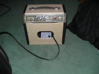
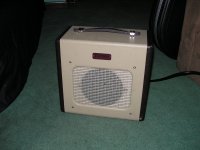
Here is a Fender Champ 600 I just modified. I added bass and treble controls, swapped the chinese 6V6 for an RCA, changed the grill cloth, and added a Jensen P6V alnico speaker. This amp truly sounds great now!!!
Good tone that won't break your back
Good tone that won't break your back
Attachments

@famousmockingbird: that champ looks great!
I tried mine with a 6L6 and it sounds fantastic... I have a KT66 somewhere that I might try too. I *should* be able to get just enough out of the bias control for it.
Building the cab has stalled. Hopefully I'll get on it this weekend.
I tried mine with a 6L6 and it sounds fantastic... I have a KT66 somewhere that I might try too. I *should* be able to get just enough out of the bias control for it.
Building the cab has stalled. Hopefully I'll get on it this weekend.
Hello lightreel, I am glad you got your issue figured out with your build. Was the cap that failed new? If it was new why did it fail? You can hook up a meter in series with the negative side to ground of the filter cap and check AC current through it. Maybe it was just a dud. I usually try and form high voltage caps before installing them, I have been lucky as most are always good. I have heard of bad batches where caps just wouldn't form and they fail.
As for the 6L6 I don't think the Champ 600 PT will take the extra heater current but it would be fun to try it.
Keep us posted on the cab build.
Rock on!! \m/
-bird
As for the 6L6 I don't think the Champ 600 PT will take the extra heater current but it would be fun to try it.
Keep us posted on the cab build.
Rock on!! \m/
-bird
As for the 6L6 I don't think the Champ 600 PT will take the extra heater current but it would be fun to try it.
I had a Vibro Champ when I was in middle school. It was about 1966 or 1967 and it was a couple of years old when I got it. The guitar player in our "band" got new stuff for Christmas one year and sold me the Champ and a Hagstrom real cheap.
I removed the 5Y3 and stuck some silicon diodes in the socket and put a 6L6GC in place of the 6V6GT. It played like that for over a year, but died within a month after I stuffed in a big fat tube in that I pulled from a Hammond organ cabinet. I now believe that tube was a 6550. Yes the power transformer fried, so I put a bigger one in, but went back to the 6L6GC because it sounded better. OPT saturation maybe? I don't know, I didn't understand those things so well then.
I made several (10 maybe) " Turbo Champs" in the late 90's. Depending on power transformer choice (Allied or transformers removed from HP audio oscillators) I would use 6V6's, 6L6GC's, EL34's, or KT88's. My preference was for the KT88 and a big speaker (one or more 12 inchers).
Things I have learned:
1. PSU Designer does not appear to model voltages correctly for solid state bridge rectifiers - it's very possible I'm doing it wrong - but I believe it incorrectly uses the same values as a full-wave rectifier. In reality, the rectified voltages are approx. 1.4x VAC coming off a bridge and 0.7x coming off a center-tapped full-wave... This meant two things: my PT could be either run waaaay over-spec'd or somewhat under-spec'd. I decided to run it under. I can still bias 6V6 and 6L6 nicely and the VVR is a *LOT* happier. I'm really thankful I had the VVR in from the start (and I was able to ease in voltages) otherwise I would have blown the hell out of a lot of components!
Voltage comparison:
BRIDGE rectifier (370DAX, 240V primary)
- HT VAC: 538
- peak DC: 759 (!)
- moderate load DC: 664
FULL WAVE rectifier (370DAX, 230V primary)
- HT VAC: 574
- peak DC: 407
- moderate load DC: 356
2. The VVR works brilliantly, but was quite noisy without a cap before it. I ended up putting a 100u 600V across the rectifier which helped massively. Amp is unbelievably quiet now... unless, weirdly, I turn the VVR pot all the way up - I suspect it's a "feature" of this particular Allen Bradley: a dead spot at the end, hum increases, voltage does not. It's no big deal.
3. I'm glad I overspec'd the PT and OT in terms of heater and bias. I'm having lots of fun rolling tubes: hopefully I'll get time tomorrow to try a KT66.
4. The moonlight tonestack is very nice, but quite subtle. My ears match the graphs I've seen: bass is pretty much unaffected, tone rolls up or down the treble. The presence control really helps shape it to taste, but I might try something to eek out even more treble and roll off a bit more bass.
I still plan on posting a "final" version of my schematic and layout. Stay tuned.
A subtle tone stack is good! Means you're not DRASTICALLY changing the signal and that the rest of the circuit works well on its own
For PSUD I've found it works quite well for no-load conditions. Almost spot on for my applications anyway. I've not yet had time to compare loaded data to tweaks in PSUD to see what I need to do for more realistic sims. In all though, its just a tool and if you get different real world results then its no big deal!
Glad to hear everything worked out in the end Just before t-day break I picked up a chassis and cab for mine. I've got my components all scribbled out on the chassis but sadly it will have to wait. Another business trip coming up here tomorrow.
For PSUD I've found it works quite well for no-load conditions. Almost spot on for my applications anyway. I've not yet had time to compare loaded data to tweaks in PSUD to see what I need to do for more realistic sims. In all though, its just a tool and if you get different real world results then its no big deal!
Glad to hear everything worked out in the end
Just before t-day break I picked up a chassis and cab for mine. I've got my components all scribbled out on the chassis but sadly it will have to wait. Another business trip coming up here tomorrow.Things I have learned:
1. PSU Designer does not appear to model voltages correctly for solid state bridge rectifiers - it's very possible I'm doing it wrong - but I believe it incorrectly uses the same values as a full-wave rectifier.
With PSUD, you need to look in the details (via the Help file) for the transformer info - it's not obvious at all. For your 260-0-260v transformer, you need to enter 260 as the transformer voltage for a full-wave rectifier using the CT, but 520 when using a bridge.
- Status
- This old topic is closed. If you want to reopen this topic, contact a moderator using the "Report Post" button.
- Home
- Live Sound
- Instruments and Amps
- "Best" Champ / Princeton schematic?