Hi,
I built the first version of this amp in 2013, but I was never quite satisfied with the results (it was my first tube project, and you know how it is with first projects). When I finally got around to fixing the things that bothered me, I unsurprisingly ended up rebuilding the whole thing pretty much from scratch. This amp is designed for bass, but it works very well with guitar too.
This time I'm very satisfied, so I thought I'd share this project in hope that it can be of use for somebody. Feel free to build this project or clone parts of it, or whatever. The schematic and layout chart should be correct, although you will have to fiddle with the power supply resistors to match your power trafo.
One of my main goals was to make a silent design (my old version was a bit hum prone), so I paid attention to lead dressing, included a humdinger in the heater supply and put in circuitry to separate audio and chassis ground. The tubes are TAD low noise tube, and the power trafo is a toroid. It also has a (ground liftable) DI output. It's not HiFi-silent, but plenty silent enough for stage or even studio work. The slight hiss from the resistors is the loudest noise, and that's fine by me.
I decided not to invent the design ground up, as I didn't have the time needed for this kind of trial-and-error approach. Instead, I wanted to find a proven design and use that as template for this build. After browsing through lots of schematics and listening to youtube reviews of different vintage tube amps, I landed on the Marshall JCM 800 Bass Series. The preamp stage is simple enough, and it seemed to have an interesting tone stack (not a fender type, which I dislike in a bass amp). You can check out the JCM schematic here for reference: Marshall-JCM800-1986.gif
I did some small modifications, and substituted the phase inverter with another gain stage and a cathode follower for low impedance output. The extra gain stage is a bit redundant, and I had to tame the gain a bit not to get to much overdrive, but it ended up working fine. (Also, I couldn't come up with any other use for the left over triode from the cathode follower).
Schematic:
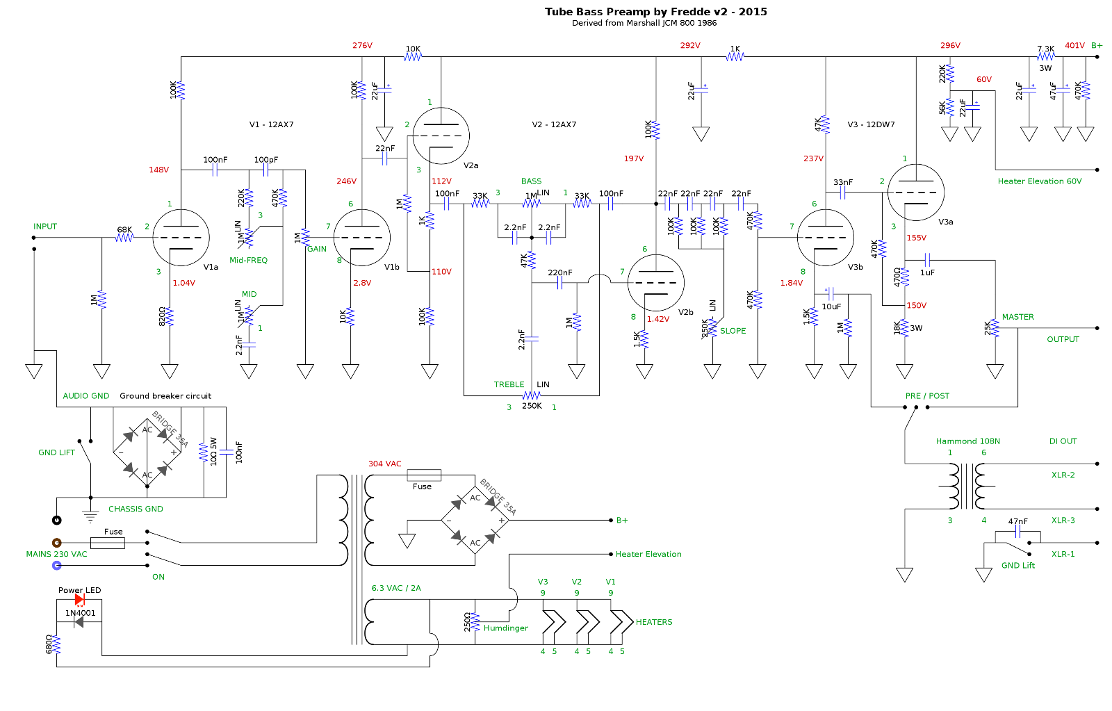
The tubes are V1: TAD 12AX7WA-R, V2: TAD 7025 WA and V3: TAD 12DW7/7247. The voltage from this trafo is a bit high so the first supply filter stage is a bit drastic with a voltage drop of over 100V, but this was the trafo I had handy. Also, being a toroid and rated for 100mA, the current draw of this amp is not enough to drop the voltage to the nominal 280VAC. For a similar build, you could go with a smaller power trafo.
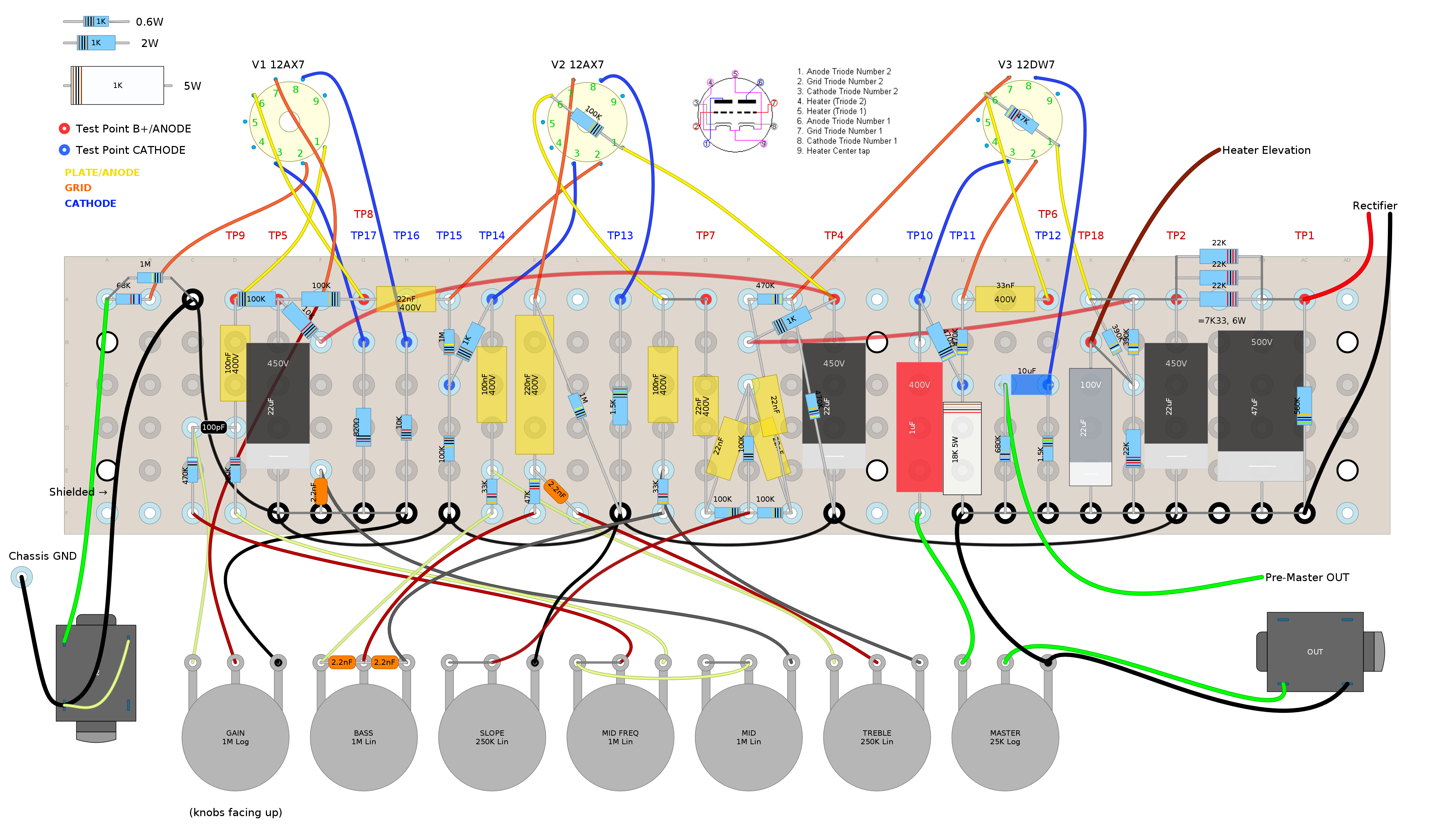
Layout:
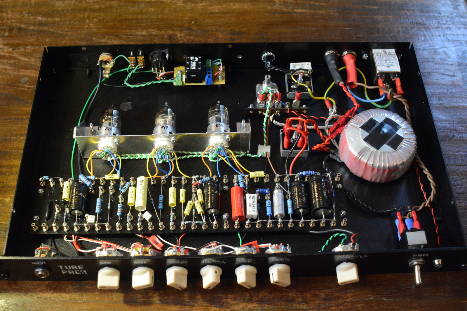
Guts:
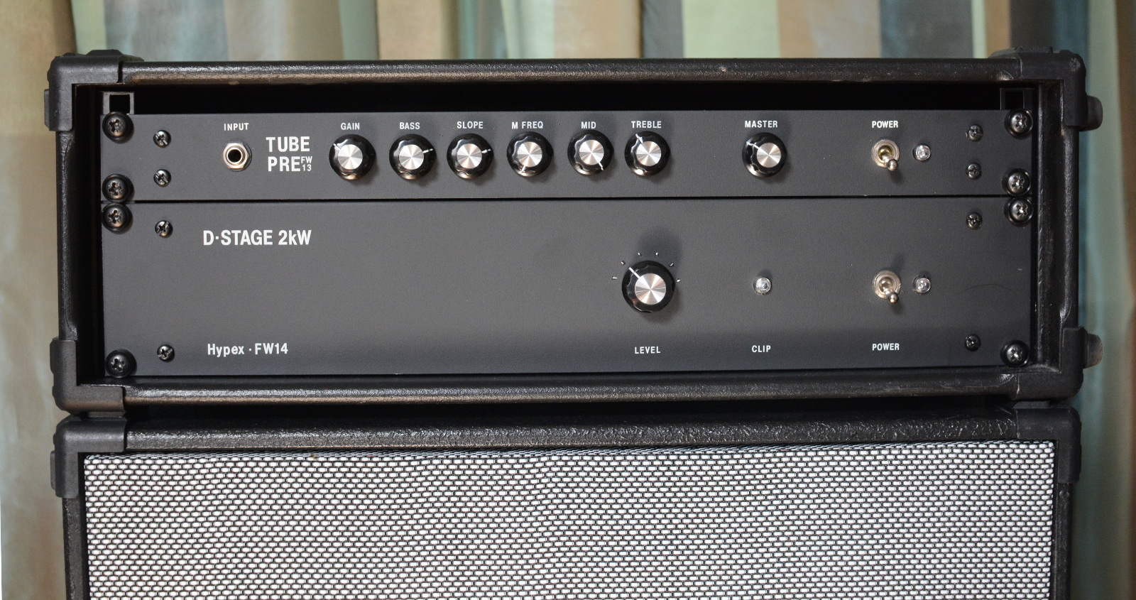
This is what it looks like in the rig, with new knobs and labels (the power amp shown is another project of mine, built around a Hypex UcD2k, more info in this thread: Hypex UcD2kOEM Bass Power Amp Project)
I'd be happy to answer any questions!
/Fredde
I built the first version of this amp in 2013, but I was never quite satisfied with the results (it was my first tube project, and you know how it is with first projects). When I finally got around to fixing the things that bothered me, I unsurprisingly ended up rebuilding the whole thing pretty much from scratch. This amp is designed for bass, but it works very well with guitar too.
This time I'm very satisfied, so I thought I'd share this project in hope that it can be of use for somebody. Feel free to build this project or clone parts of it, or whatever. The schematic and layout chart should be correct, although you will have to fiddle with the power supply resistors to match your power trafo.
One of my main goals was to make a silent design (my old version was a bit hum prone), so I paid attention to lead dressing, included a humdinger in the heater supply and put in circuitry to separate audio and chassis ground. The tubes are TAD low noise tube, and the power trafo is a toroid. It also has a (ground liftable) DI output. It's not HiFi-silent, but plenty silent enough for stage or even studio work. The slight hiss from the resistors is the loudest noise, and that's fine by me.
I decided not to invent the design ground up, as I didn't have the time needed for this kind of trial-and-error approach. Instead, I wanted to find a proven design and use that as template for this build. After browsing through lots of schematics and listening to youtube reviews of different vintage tube amps, I landed on the Marshall JCM 800 Bass Series. The preamp stage is simple enough, and it seemed to have an interesting tone stack (not a fender type, which I dislike in a bass amp). You can check out the JCM schematic here for reference: Marshall-JCM800-1986.gif
I did some small modifications, and substituted the phase inverter with another gain stage and a cathode follower for low impedance output. The extra gain stage is a bit redundant, and I had to tame the gain a bit not to get to much overdrive, but it ended up working fine. (Also, I couldn't come up with any other use for the left over triode from the cathode follower).
Schematic:
The tubes are V1: TAD 12AX7WA-R, V2: TAD 7025 WA and V3: TAD 12DW7/7247. The voltage from this trafo is a bit high so the first supply filter stage is a bit drastic with a voltage drop of over 100V, but this was the trafo I had handy. Also, being a toroid and rated for 100mA, the current draw of this amp is not enough to drop the voltage to the nominal 280VAC. For a similar build, you could go with a smaller power trafo.
Layout:
Guts:
This is what it looks like in the rig, with new knobs and labels (the power amp shown is another project of mine, built around a Hypex UcD2k, more info in this thread: Hypex UcD2kOEM Bass Power Amp Project)
I'd be happy to answer any questions!
/Fredde
Cool, I asked you for this in the other thread , hadn't seen it before.
Congratulations on an excellent build 🙂
Congratulations on an excellent build 🙂
Cool, I asked you for this in the other thread , hadn't seen it before.
Congratulations on an excellent build 🙂
Thank you!
Last edited:
I used Letraset rubdown transfer sheets (these: http://www.letraset.com/products/90-Letraset-Transfers/ )
You don't have a lot of options with a black surface (laser printable water decals won't work), and this is the best I've come up with so far. Problem is, last time I used these I noticed they scratch pretty easily and look quite bad after some months of use. This time I used a matte spray lacquer as a sealant on top of the labels and this seems to do the trick (only time will tell).
http://www.letraset.com/products/90-Letraset-Transfers/
Very nice work! Would love to hear clips of it.
If you're not a member already check out the talkbass amp forum. Someone will probably want to buy one.
If you're not a member already check out the talkbass amp forum. Someone will probably want to buy one.
Heh, I'm not sellin' 😉 But yes, I'm a member there.
My summer vacation is over now, but I'll see if I have time to record clips at some point.
My summer vacation is over now, but I'll see if I have time to record clips at some point.
Ok, I've recorded some clips.
Bass: Fender Precision AVRI '57 1982
Strings: DR Nickel Lo-riders (pretty old)
Recording: Passive DI-BOX and USB-soundcard, no processing.
The clips in the file organized as follows:
1 - Bass directly to soundcard (no preamp)
2-5 - Clean sounds
6-8 - Overdriven sounds
The clips: Amptest.mp3 (1 min 14 sec, 1Mb)
(Voice recording Copyright 2012 Iwan Gabovitch [http://qubodup.net])
Thanks Freddie,
I just made one. I basically followed your design, but had to use a voltage doubler
To get the HV high enough as I had had a low voltage power transformer, and larger filter caps to allow for the ripple.
I was really happy how it worked out.
Mine is not as good looking as yours as I used an old rack case, and bits and pieces that I had been scrounging for years. The result sound wise is great very much a keeper
Thanks for posting your build.
Thanks Freddie,
I just made one. I basically followed your design, but had to use a voltage doubler
To get the HV high enough as I had had a low voltage power transformer, and larger filter caps to allow for the ripple.
I was really happy how it worked out.
Mine is not as good looking as yours as I used an old rack case, and bits and pieces that I had been scrounging for years. The result sound wise is great very much a keeper
Thanks for posting your build.
Wow, cool! Glad to hear this design worked out for you! Got any pics? Also, care to share the details about the voltage doubler, how much additional ripple filtering did you put in, and did it get silent enough? If you have a schematic of your version of the PSU, please share it here, maybe it can be of use to somebody else.
I have another project going (converting an earlier solid state build to have a tube preamp stage), and my first plan was to use the existing transformer with voltage doublers for the B+. But there wasn't room in the chassis for all the additional filter caps (and a regulator for the heater voltage), so I bit the bullet and ordered a custom wound toroid. (Again...)
I will just finish the final details and I'll post the results.
Im not as neat as you are, but I will definitely share the results
Im not as neat as you are, but I will definitely share the results
getting to finished stage
Hi Freddie
Sorry for the late reply, its taken me this long to get back to the project.
Mine had a little noise, so I chose to go DC on the filament heaters.
As my transformer has a dual 6.3 volt ac windings
I series the windings creating 12.6 volts with a centre tap
I used the centre tap for heater elevation,
went through a rectifier, filtered then a 7806 regulator with a 1n4148 on the centre leg of the regulator to take me over to 6.2 volts.
The DC from the regulator I left floating to the tube filaments as it was already referenced by the heater elevation through the centre tap winding.
The final verdict "she's a keeper" nice and quiet with lots of useable sounds
I will take some photos, In fact I thought I did until I checked my camera
and they were not there.
I wish now I put it in a pretty box, maybe I might drop the guts out and do that.
Very happy with the result
I have attached some images. Not sure if I am doing this right.
Mineis not as nice as Freddies. Mine was put together for customers who need a bass amp while theres are in for repair.
It sounds great. I had a old Amcron I bridged it to get plenty of grunt out of it
Thanks Freddie for posting the build
Mineis not as nice as Freddies. Mine was put together for customers who need a bass amp while theres are in for repair.
It sounds great. I had a old Amcron I bridged it to get plenty of grunt out of it
Thanks Freddie for posting the build
Attachments


Nice work Brendan! I'm glad you are happy with the design!
It's good you managed to solve your hum problem with the DC heater, so no point in changing anything now. But I see one possible cause of the problem. The signal leads between the board and the tube sockets looks to run parallel to the heater wires. This is known to induce hum. I've read* that signal wires should be kept as far away from the heater wires as possible, and ideally make 90 degree crossings if they have to cross. Also, did you have a humdinger pot before switching over to DC heaters?
But this is all academic as you managed to solve the problem. And don't get me wrong, this looks really good!
*I think it was in this book: Designing Tube Preamps for Guitar and Bass
by Merlin Blencowe
Last edited:
Did someone tried the schematic only with 12AX7 tubes?
No - but I don't see any major compromise in doing so.
As you probably know a 12DW7 is 1/2 a 12AX7 and 1/2 a 12AU7 in one envelope.
pins 6,7 and 8 are the 12AX7 triode section (V3B) and pins 1,2 and 3 are the 12AU7 triode section (V3A).
Just modify the circuit of V3A to look exactly like V2A and you can use a 12AX7 for V3. Output Impedance from V3A cathode will be a little higher and it may benefit from increasing the MASTER pot to 50K but should be OK with the 25K.
Cheers,
Ian
Last edited:
It makes me happy that people want to try different modifications on this amp! My only request: please report back if you make a successful (or failed) mod so that others might benefit from it. Post a schematic if you have one, or take the original schematic and draw in the changes you've made. Maybe we'll end up with a new and improved design. Cheers!
The 25k master is probably a bit overkill impedance-wise, anyway. Most power amps can take way higher impedances, and usually the cable between the pre and power amp is very short. A 50k pot would also lower the corner frequency, so you could switch to a smaller output cap (470n) saving money and space. Even 220n would be enough (the output cap is also a bit overkill in my schemo... I like overkill 🙂 )
Another thing: Current draw is higher on the 12WD7 (because of the 12AU7 triode), so if you swap it out for a 12AX7 you will get higher plate voltages on the preceding stages (more headroom = won't overdrive as easily). I don't know by how much, maybe it won't even be noticeable (can't bother to do the math), but I would just try and see how it works out.
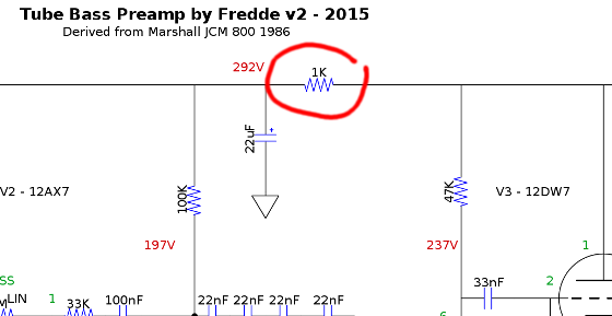
If keeping the original voltages is important, you could try increasing the the 1K supply filter resistor shown here:
No - but I don't see any major compromise in doing so.Did someone tried the schematic only with 12AX7 tubes?
As you probably know a 12DW7 is 1/2 a 12AX7 and 1/2 a 12AU7 in one envelope.
pins 6,7 and 8 are the 12AX7 triode section (V3B) and pins 1,2 and 3 are the 12AU7 triode section (V3A).
Just modify the circuit of V3A to look exactly like V2A and you can use a 12AX7 for V3. Output Impedance from V3A cathode will be a little higher and it may benefit from increasing the MASTER pot to 50K but should be OK with the 25K.
Cheers,
Ian
The 25k master is probably a bit overkill impedance-wise, anyway. Most power amps can take way higher impedances, and usually the cable between the pre and power amp is very short. A 50k pot would also lower the corner frequency, so you could switch to a smaller output cap (470n) saving money and space. Even 220n would be enough (the output cap is also a bit overkill in my schemo... I like overkill 🙂 )
Another thing: Current draw is higher on the 12WD7 (because of the 12AU7 triode), so if you swap it out for a 12AX7 you will get higher plate voltages on the preceding stages (more headroom = won't overdrive as easily). I don't know by how much, maybe it won't even be noticeable (can't bother to do the math), but I would just try and see how it works out.
If keeping the original voltages is important, you could try increasing the the 1K supply filter resistor shown here:
Fredde, I know this is an old thread. I am considering this for my first tube preamp build. Is there anything in the last few years you'd recommend changing? Thanks
I just finished my first electronics build of any substance. I built a preamp off of Fredde’s plan. Used a Genalex Gold Lion 12AX7 for V1 and V2 and. JJ 12DW7 for V3. My B plus was 435V so I changed the 3 parallel 22k resistors (net 7.3k) for 3 parallel 27k for a net 9k. Puts it right on the dot.
Preamp - Album on Imgur
Preamp - Album on Imgur
- Home
- Live Sound
- Instruments and Amps
- Build report: Tube preamp for bass (or guitar)