Working on a '36 Mill jukebox 42990 amp and am looking for a good place to purchase caps, electrolytics and resistors. Pretty straightforward repair, but need a schematic listing the values, especially the resistors, which are the dogbone style: green w/orange dot; solid pink; brown w/ylllow dot; orange w/yellow dot; yellow w/orange dot; brown w/orange dot. Any info would be greatly appreciated. Thanks! E.T.
Unless you want all those resistors replaced with the exact same looking parts, resistors are available at any general electronics parts house, like Mouser or Digikey. As are caps of all sorts. No one has made dogbone resistors in decades.
Today we have standard values numbers, so for example 220k resistor is a standard value, while say 230k is not. SO back then, they may have used what were to them common values that today are not, so maybe a 250k resistor. The values are not critical, so a 220k would work just as well for you. It is only a juke box, not a NASA lab equipment. Same with caps, Voltage made caps expensive back then, so you might find a cathode bypass cap rated for 6v. Good luck finding a 6v cap these days, but a 16 or 25v cap would be just fine in its place. And again, standard values have changed, so if a 20uf or 25uf is harder to find, use a standard 22uf from any supplier.
If you don't know how to read those colors, the colors themselves are the same as today. The old resistors used the body color, the end color, and the dot, just as we now use the first, second, and third stripe.
Here: RESISTOR COLOR CODES
So you have the solid body color adn dot, but please check to see if one end is painted a different color.
I have been restoring old jukes for decades, so I wish you well, seems to me 1936 or 1938 thereabouts is about the oldest ones I have rebuilt. Fortunately, the amps tended to be a LOT simpler then. I had no trouble tracing them out by hand.
I do not know your skill level, so aside from standard value issues, they did not use "picofarad" back them, we used "micro-microfarad" instead, usually written mmf and then uuf. And no one used nanofarad. Or millifarad. Geez, a millifarad is 1000 microfarads, and caps just didn't get that big. So don't be confused by those terms.
If you cannot read some value, once you have traced the circuit, we shouldbe able to infer a reasonable value from the circuit.
If you haven't traced a circuit before, it isn't hard. I start with the tube types. Basic circuit topology hasn't really changed all that much, a push pull output stage will look familiar,as will a triode gain stage. The tubes might have 4-pin or 5-pin bases instead of octal, but that's no problem. So what I do it start with the tubes, I draw them on a page, then I start looking at each tube pin and follow each of its connections out to something. For instance, a triode plate probably has a largish resistor (100k, 250k, etc) to the B+, and also a coupling cap to the next stage. A tetrode or pentode power tube probably has the transformer wired to its plate, and some sort of B+ connection to its screen, maybe through a resistor. Most likely cathode biased output stage, so a power resistor, maybe with parallel cap, from the cathodes to ground. There are data sheets or at least tube base diagrams for all the old tubes, easily found.
My juke library has pretty good coverage of Seebergs from the 1950s on, but most of the WW2 and earlier stuff I have is all hand drawn. I don't know that I have any Mills ones in my files.
Thank you Enzo for your input. I have restored around 25 radios dating from 1929-1942 over the course of the last 7 years (that includes an 11 tube Philco 42-400 rolltop console which was a complete basket case and needed total re-wiring, caps, electros, resistors. And, someone cut wires all over. Plus, the best schematics were incomplete. No easy task -she turned out fantastic!). I also bake and re-stuff all my caps to the original golden "juiciness". Originality to me is very important. I will make the dogbone mold and construct and paint them. I always had a schematic listing the values of the occasional dogbones-some Philco resistors had propriatary colors on their resistors, and thought perhaps Mills was the same way. When I pulled this chassis out, I actually laughed at how simple it was. Also have the book w/ schematics, but it lists no component values-just Mill part #'s. Just need a good place to buy CHEAP components, and resistor values. Everything else is cut and dry. thanks for your reply. E.T.
OK, if you are that hard core about it - and I mean that kindly - and are looking to make a museum piece rather than a simply working circuit...
Unless you want to buy in the antique/collectors market, there have been no dogbone resistors for eons. But I see nothing preventing you from molding epoxy or resin of some sort around a modern resistor. And those caps that look like dominoes? MAybe a similar trick. My juke restorations were always just for operation, cosmetics were not a consideration, so you are in a land I have not explored.
Again, places like Mouser are where I shop for common parts. I also work in pro audio so I service endless numbers of tube guitar amps. Some of the higher voltage caps and other amp specific parts I will also shop at Antigue Electronic Supply,
www.tubesandmore.com
You may be familiar with them if you do old radios, they do sell parts for those too.
thanks once again, Enzo. That is the info I was looking for. I've been off line for a couple of years now, but feels like a million. It seems as if my memory has "crashed" as of late, so forgive the rudimentary questions. I've always re-stuffed all my caps from day one, though no one will probably ever see the guts of this thing for the next 79 years, I wont do the job otherwise. This is my first full-blown jukebox chassis and just basically need to know info such as: a) the tubes are fast acting, so therefore do I need to also get those "fast acting" caps? b) what style resistors and caps are the best for these jukes? Any of that kind of information is greatly welcomed. There is much to be said about the old "apples to oranges" comparison test.
No, silver micas came much later.
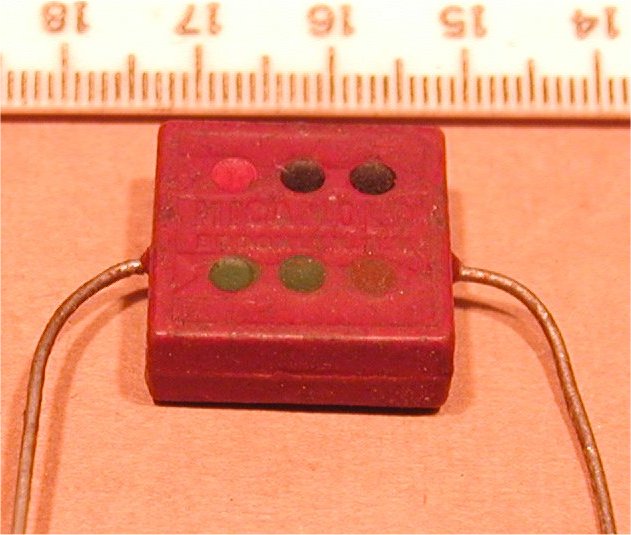
There were mica caps in the domino form, smaller ones, they are pretty reliable, but the larger ones were paper or other common at the time materials. They can be as large as actual dominos.
Here is one chart of codes, they are on the right down a ways.
Reading Color Codes for Resistors and Capacitors
Note there were several code arrangements, so you had to determine which system you were seeing by the context.
I don't know what you mean by fast acting tubes. They are just tubes, and they are operating in audio, so no high frequencies. Nor do I know what fast acting caps might be. There is no need to use components specified for high radio frequencies. it is just a basic audio amp. Plain old common cap types will work fine. Remember this was 1936, not 2006. So even if their marketing uses terms like fast acting, consider what might have been fast back then.
Your circuit was built before there were caps with radial leads - unless you consider the can cap radial. Today radial are the more common. But if you replace a 0.01uf 400v cap, you will likely want to replace it with an axial leaded cap. So when ordering, remember that.
DogBone Resistors
Seems that dogbone resistors are in short supply worldwide.
JOBLOT 60 VINTAGE ERIE DOGBONE CARBON RESISTORS VALVE AMPLIFIER & RADIO REPAIRS | eBay
JOBLOT 60 VINTAGE ERIE DOGBONE CARBON RESISTORS VALVE AMPLIFIER + RADIO REPAIRS | eBay
Andy
Seems that dogbone resistors are in short supply worldwide.
JOBLOT 60 VINTAGE ERIE DOGBONE CARBON RESISTORS VALVE AMPLIFIER & RADIO REPAIRS | eBay
JOBLOT 60 VINTAGE ERIE DOGBONE CARBON RESISTORS VALVE AMPLIFIER + RADIO REPAIRS | eBay
Andy
I fully intend to re-stuff the 2 metal electrolytic cans, et al. I have always used axial leads. Don't like radial lead caps. Never have, never will. Even when stuffing the metal cans. I guess we got onto that Philco tangent which isn't even pertinent to this subject. Obviously I'm trying to read more into it than necessary, as this is about one of the simplest chassis I've ever worked on. 
For out in the point to point stuff axials rule. For restuffing the cans, I would have thought radials would be preferred - all the leads would be handy at the bottom. Personal preference, I guess.
If you find a stash of old dogbone resistors, even if unused, they are still 60-70-80 years old. And that 250k might measure who knows 400k. SO we would need to check each part. If you have the ambition to mold covers for new parts, then that is moot.
I had a customer once who needed a male connector he couldn't find, so he turned one out of a piece of maple and formed pins from piano wire stock. More motivation than I have, I'll say.
I haven't seen them often, but in that era there were sometimes combined components. They were like a cap and resistor in parallel in a rectangular form similar to the dominoes.
Hi all, back again. Hope everyone had a great 4th. A little update on the old project. Well, I gutted all of the capacitors and electrolytics, including the 2 metal cans and restuffed all, inserting them back into nearly the exact positions from whence they came. I also fabricated new dogbone resistors by hand (didn't make any molds), which weren't exactly perfect, but gives an overall flavor of yesteryear. Here is a before and after shot of under the chassis:
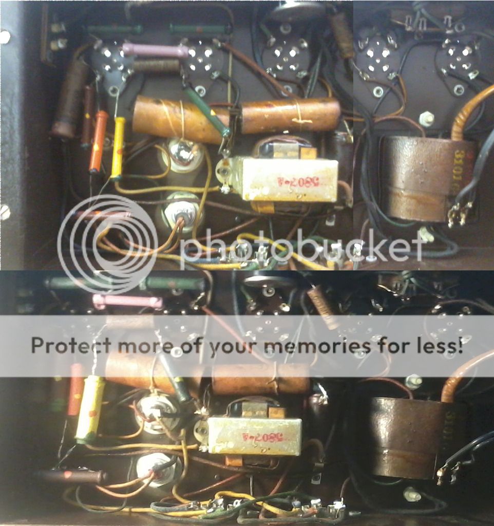
yes, the new resistors are larger, due to the fact that I used 2 and 3 watters instead of what was originally there. (Had the schematics in the ancient book, but it only listed the Mills part #'s, so I went to overkill mode- especially when you look at that gaudy yellow 5 watt job *UGLY*, but passable). Also due to the fact that the comparison images were taken at two different angles, we had to do a little forensics to correct the angle on the before photo, as seen near the power transformer. Okay, here's what we got: she turns on and plays much louder than when my boss plugged it in and tried it originally (egad). problem is my # 30 and #32 tubes are not lighting up. Have not checked current voltage due to this:
Also, I was so focused on the chassis, I never dreamed this would be mounted in the cabinet:
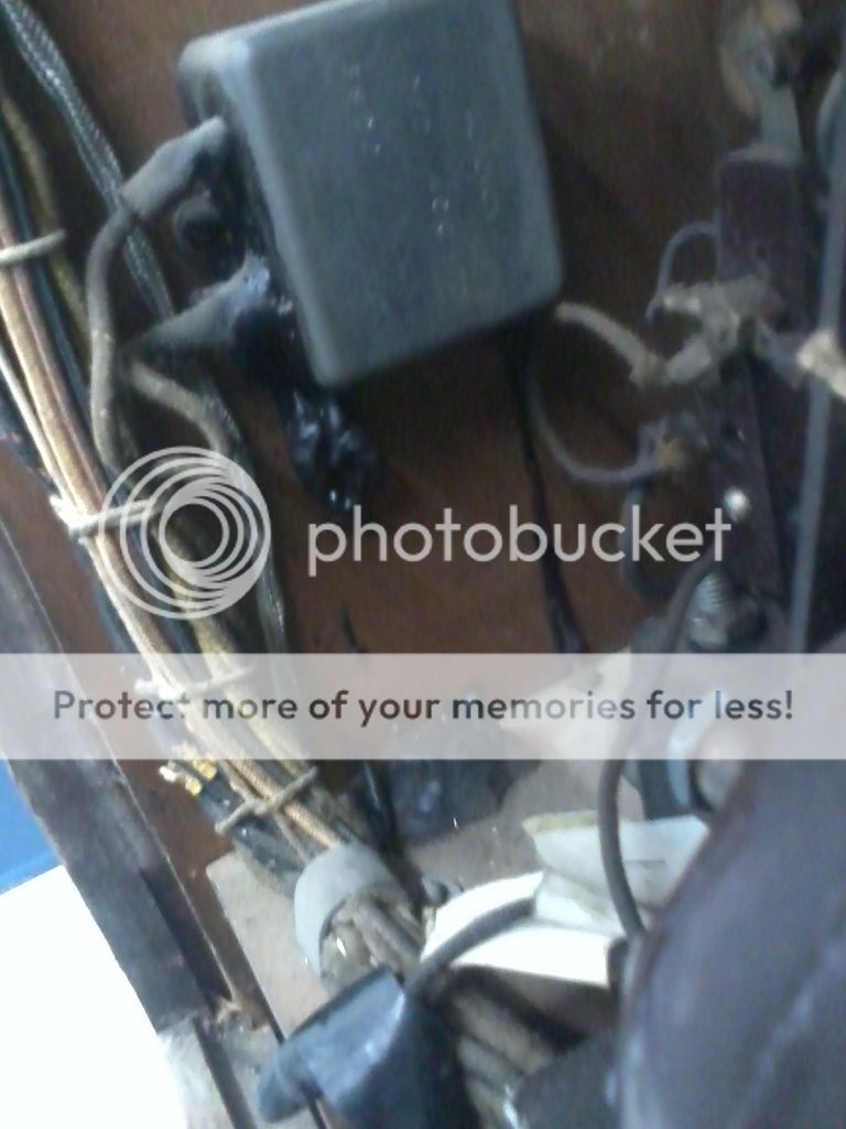
1 microfarad @ 400v. Leaking, tested dead in the circuit. Removed and tested- .8mfd-well within tolerance!!! WHAT TH'... One more little thing: are there caps in this box closest, on the left side (my gut is leading me there):
I believe all my connections are good and well soldered. We have fully tested new old stock tubes (2 of them cost $85 apiece). That leaking electrolytic in the cabinet obviously is getting hot, wondering if that may be the culprit? (Hate to unwind that original beautifully strunged string harness. Any suggestions? Will add all photos into photo bucket soon, if anyone is interested. Thanks for letting me bend your ears!
yes, the new resistors are larger, due to the fact that I used 2 and 3 watters instead of what was originally there. (Had the schematics in the ancient book, but it only listed the Mills part #'s, so I went to overkill mode- especially when you look at that gaudy yellow 5 watt job *UGLY*, but passable). Also due to the fact that the comparison images were taken at two different angles, we had to do a little forensics to correct the angle on the before photo, as seen near the power transformer. Okay, here's what we got: she turns on and plays much louder than when my boss plugged it in and tried it originally (egad). problem is my # 30 and #32 tubes are not lighting up. Have not checked current voltage due to this:
Also, I was so focused on the chassis, I never dreamed this would be mounted in the cabinet:
1 microfarad @ 400v. Leaking, tested dead in the circuit. Removed and tested- .8mfd-well within tolerance!!! WHAT TH'... One more little thing: are there caps in this box closest, on the left side (my gut is leading me there):
I believe all my connections are good and well soldered. We have fully tested new old stock tubes (2 of them cost $85 apiece). That leaking electrolytic in the cabinet obviously is getting hot, wondering if that may be the culprit? (Hate to unwind that original beautifully strunged string harness. Any suggestions? Will add all photos into photo bucket soon, if anyone is interested. Thanks for letting me bend your ears!
There is no reason to undo the wire harness. You can disconnect the ends of the wires from whatever they conect to.
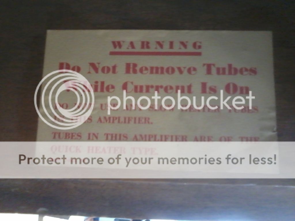
The warning? relax. it says do not remove tubes with current on. That means turn the thing off before you pluck tubes from the sockets.
I see in the underside, near the center, a couple of what look to be caps. The things with string tied around them. Have you checked to see if DC is leaking through them? And one of those, the one on the right, is just above a small transformer or choke. Now immediately upper right from that cap is what looks to be a smaller cap. Tan color, has a stripe near the bottom end, sits at an angle, wired to a tube socket at the lower end. That looks to be an old wax cap from here, and almost certainly would be leaky.
That 1uf/400v bathtub cap is not electrolytic, just an oil filled cap. But whatever it is, a plain old vanilla 1uf 400v cap will work there. If you feel like grinding it open, I am sure you could hide a modern cap inside it.
If you have tubes not lighting up, then start at the heater pins and see if heater power is gettting there.
Thanks Enzo, but on that leaking cap in the cabinet, I was just wondering if that was the culprit for not allowing my #30 and #32 tubes not to alight? As I stated in the captions that I gutted ALL of the capacitors and electrolytics, and re-stuffed them with modern axials of the 630v style into the original tubes. (And yes, I re-waxed them to look completely original. The 3 electrolytics in the 2 metal cans have also been "modernized". I will make a tag stating the work performed for the next technician who works on it in the next 50-80 years from now). Those large electrolytics in the center have their original strings wrapped back around them, and have been re-waxed, to boot! That old bathtub cap is in my hand, even as we speak. Just seemed very peculiar that she was leaking (obviously getting hot), but still tested WELL within tolerance of 1mfd. I recon under load that she is failing. I will re-stuff this also. The real crux is that box in the topside left hand corner of the last image: are there caps or electrolytics in that unit? The two dead tubes have wires coming from that box, both directly and indirectly. I would HATE to drill those rivets out and pull it just to find out that it's a transformer in good condition, or some such nonsense. Also, when I check the voltage at the pins with the tubes out, should I also have the speakers (or anything else) connected to put a load on the circuit? the voltages may be a moot point, as I have nothing to compare them to, as the ancient schematics that I have do not list any pertinent information on the subject. Thanks for responding. E.T.
Your meter can measure the capacitance, but it does it at only a volt or two. Your 400v cap might test fine at a volt or two, but leak like a screen door at 200-300-400v. And if you were to measure ESR, you might find that out of whack too.
And yes, you did say you had restuffed your old parts, sorry.
I don't know why a cap would kill your heaters, but again, the thing to do is look for the heater voltage across the heater pins.
And yes, you did say you had restuffed your old parts, sorry.
I don't know why a cap would kill your heaters, but again, the thing to do is look for the heater voltage across the heater pins.
I doubt they would leave a whole box of caps off the schematic. But if you were to POST the schematic, we might have better answers.
If I had to figure it out, I'd find the wires coming into the chassis from the box and see what they are wired to, then compare that to the schematic.
If I had to figure it out, I'd find the wires coming into the chassis from the box and see what they are wired to, then compare that to the schematic.
Well that settles it, then. Those wires coming out of the box pretty much go to those 2 tubes, one way t'other. Looks like I'll be drilling out the rivets on the box. I will take another good look at the schematics, which If I can, I may attempt to post. I guess I'm just afraid to treat this like a regular run of the mill RADIO amp for fear of doing any damage, due to not following proper procedures. One last stupid question: Can I just plug that baby in on the bench WITHOUT the tubes & speakers installed, to at least check the voltages without doing any harm? (This is my first jukebox, though I've revived many tube radios in the past, I've always had to have the speakers attached to put a load on the system. I just want to tread very lightly with this unit). And a side note: The book shows 2 six amp fuses inside of a box with a removable cover. It also shows in the same box a separate covered section with a cylindrical 2 amp fuse. I cannot remove this cover... It has a factory style LOCK on it, which I unsuccessfully attempted to pick earlier this evening. This is not part of the coin drop box, which was removed eons ago. HMMMMM...
This is just an amp, nothing cosmic. if you work on radios, the only difference here is that there is no RF section.
You can power it up without tubes, but be aware your B+ will be absent, or if you install just the rectifier, then all B+ readings will be high due to lack of current draw. if there are no tubes in it, then it doesn't matter if there is a load. Any tube audio amp needs to have its output loaded when operating.
I hinted at it, but it would be pleasing if you would POST the schematic here.
- Status
- This old topic is closed. If you want to reopen this topic, contact a moderator using the "Report Post" button.
- Home
- Live Sound
- Instruments and Amps
- 1936 Mills jukebox