I originally posted this on another forum, but decided to post it here too as I spend most of my time here:
OK,
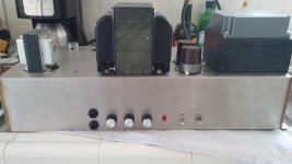
So here's my attempt at cloning the Marshall 200 "Pig" as per Vintagekiki's schematic.
I still need to label all the knobs and jacks, and I need to build a cabinet to house amp in.
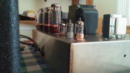
Power output tubes will be either GL KT88s or Chinese EL156s. Main B+ is 700 volts, Screen supply is 410 volts; should be enough for well over 200 watts.
The amp is very quiet with the knobs all turned up; very little hum. I did a good job with the grounds in this amp. The controls take some getting used to, they all interact with each other, when adjusting them. The one thing that I was concerned about was the treble and bass controls; I didn't think they would match up as the treble circuit is a cathode follower which has a gain of less than 1. The bass and treble controls do match up well in this amp.
I have the Chinese EL156 tubes in for the outputs (think of an EL34 on steroids). A word of warning to people buying tubes direct from China... I bought 20 of these tubes and 8 of them are bad, right out of the box. Spend the extra money and buy tubes from a reputable dealer... That's what I get for being cheap...
Many thanks to Vintagekiki for his work on the schematic he provided. I looked at all links he provided for circuit information and I think he did a great job tracing out the schematic onto paper.
If anybody on this board lives in the Los Angeles area, namely, the Hollywood - North Hollywood area of L.A., PM me if you want to give this amp a try to see how it sounds.
PS. Does anyone have outside measurements of the "Pig" cabinet? I'm looking for length X width X height dimensions... Thanks.
EDIT: I tried uploading pictures but got an error saying "security token missing". I sent pics to Admin; hopefully they can add the pics. >>>>FIXED BELOW<<<<
OK,
So here's my attempt at cloning the Marshall 200 "Pig" as per Vintagekiki's schematic.
I still need to label all the knobs and jacks, and I need to build a cabinet to house amp in.
Power output tubes will be either GL KT88s or Chinese EL156s. Main B+ is 700 volts, Screen supply is 410 volts; should be enough for well over 200 watts.
The amp is very quiet with the knobs all turned up; very little hum. I did a good job with the grounds in this amp. The controls take some getting used to, they all interact with each other, when adjusting them. The one thing that I was concerned about was the treble and bass controls; I didn't think they would match up as the treble circuit is a cathode follower which has a gain of less than 1. The bass and treble controls do match up well in this amp.
I have the Chinese EL156 tubes in for the outputs (think of an EL34 on steroids). A word of warning to people buying tubes direct from China... I bought 20 of these tubes and 8 of them are bad, right out of the box. Spend the extra money and buy tubes from a reputable dealer... That's what I get for being cheap...
Many thanks to Vintagekiki for his work on the schematic he provided. I looked at all links he provided for circuit information and I think he did a great job tracing out the schematic onto paper.
If anybody on this board lives in the Los Angeles area, namely, the Hollywood - North Hollywood area of L.A., PM me if you want to give this amp a try to see how it sounds.
PS. Does anyone have outside measurements of the "Pig" cabinet? I'm looking for length X width X height dimensions... Thanks.
EDIT: I tried uploading pictures but got an error saying "security token missing". I sent pics to Admin; hopefully they can add the pics. >>>>FIXED BELOW<<<<
Last edited:
hope ya get ya pics upbe nice to have a look
do you have the cookies turned off in your browser, if so this might be why you can't load pics and posting to the site is good. There's not much worse than going back to a thread (that you knew had an answer you need) only to find all the pics are dead links to photo bucket or sum such.
Sorry for this hijack, just one of my personal peeves.
I have the History of Marshall book by Michael Doyle and he has a few pics of it in there. There is probably 3" or so between the end of the chassis and the cab, so they must have used the same cab as the model 1959 100 watt amp except they"were slightly larger than the 100 watt heads, 11" vs. 8 1/4" deep to accommodate the transformers" and of course, the small control knob opening. Sorry, that's all I could find. They didn't make many of these a before they evolved in to the Major Model. Not much info to be found it appears.
") I can see the bottle in one of your pics.
I can see the bottle in one of your pics. I have the History of Marshall book by Michael Doyle and he has a few pics of it in there. There is probably 3" or so between the end of the chassis and the cab, so they must have used the same cab as the model 1959 100 watt amp except they"were slightly larger than the 100 watt heads, 11" vs. 8 1/4" deep to accommodate the transformers" and of course, the small control knob opening. Sorry, that's all I could find. They didn't make many of these a before they evolved in to the Major Model. Not much info to be found it appears.
Hi, I found the cabinet dimensions after a google search. It's 29"W X 10.875"H X 11"D. Same as the Marshall Major; only difference is the cutout on the front panel is smaller in the "PIG" amps. And, yes, you are correct... Cabinet is basically the same size as the 100 watt Super Lead but about 3" deeper.
Thanks for looking this up in your Book.
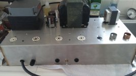
The chassis I used is Stainless Steel, Somebody gave me three of them years ago and luckily I didn't throw them out. SS is a pain to work with as it's much harder than mild steel but I think the end result is pretty good.
My Chassis is much taller than a Marshall chassis but once the amp is in a cabinet, the difference won't be noticeable.
Last edited:
Hi All - this is my first post,
Hi Dan, that is a very neat build. On the schematic, kindly reproduced by Vintagekiki, I can see that the preamp splits the highs from the lows, a bit like a tube crossover, then they are re-combined at the master volume pot, post e.q. - but the highs are in anti-phase to the lows there (not to mention mismatched in impedance) - is this the magic of the Pig?
Hi Dan, that is a very neat build. On the schematic, kindly reproduced by Vintagekiki, I can see that the preamp splits the highs from the lows, a bit like a tube crossover, then they are re-combined at the master volume pot, post e.q. - but the highs are in anti-phase to the lows there (not to mention mismatched in impedance) - is this the magic of the Pig?
Hi again - to add a little idea to my earlier post, at the master volume summing node, could frequencies that are common to both Bass and Treble channels be partially phase cancelled, i.e. it's scooped mids! Yes, No or Maybe?
Hi!
Yes, several people have noted that the 2 signals are out of phase to each other; to tell you the truth, I have never hooked it up to a oscilloscope to see for sure if the signals are truly out of phase. And counting the caps and tubes (there's even a cathode follower on one side) confuses me even more!
But yes, this would account for the scooped mids of the amp if the signals are actually out of phase. I think the high and low pass filters are 12 or 18db per octave filters; please correct me if I'm wrong. I'd also like to know what the knee frequency is for each filter... I think they are the same for both.
Nice! Is that the correct OT or did you substitute something?
Power transformer looks like Tektronix?
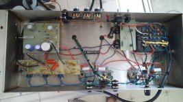
It's a hammond output transformer (1650R) used at half impedances (16 ohm tap becomes 8 ohms, etc.) which works well for 200 watts at guitar frequencies but is a little small physically if a bass guitar is used. And yes, the PT is from an old Tek scope!
Vintagekiki did a wonderful job on figuring out the schematic as Marshall had no idea what it was. Kind of funny, really. The only differences is that the plate voltage is actually 720 volts, the screen supply is around 420 volts and the feedback resistor (27K) actually goes to the 16 ohm OT secondary tap, like all other Marshall amps of that era. The original OT on the "PIG" was the Partridge TH1499; 2250 ohms primary. Heyboer in Michigan did a teardown on one of these so can wind one to exact Partridge specs.
Last edited:
- Status
- This old topic is closed. If you want to reopen this topic, contact a moderator using the "Report Post" button.
- Home
- Live Sound
- Instruments and Amps
- Marshall 200 Watt "PIG" Build