anyone know a trick to make a 12ax7(ecc83) sound like a 6sl7 or do i just give in an mount an octal socket in ma 5E3 maybe even 2 as my big amp has 6sl7 as PI as well
just so u no, I am trying to make my old 5E3 based build witch is smaller an lighter, sound like (or at least close to) my big amp which is basically a 50 watt 5c3-5E3 but bigger iron obviously. I ve put in a board with all the same componets but no mater how i play with the voltages it's just not getting there.
and yes i am using the same speaker.
Not sure if this matters enough but the 6SL7 a has an amplification factor of 70 and the 12AX7 is 100. The 5751 has a mu of 70, so this matches the 6SL7. Maybe the lower gain of the stage by having the 5751 might make some difference. And having it in the PI as well will make that much more of a difference. And of course it has the same pinout, so why not try it?
Last edited:
anyone know a trick to make a 12ax7(ecc83) sound like a 6sl7 or do i just give in an mount an octal socket in ma 5E3 maybe even 2 as my big amp has 6sl7 as PI as well
just so u no, I am trying to make my old 5E3 based build witch is smaller an lighter, sound like (or at least close to) my big amp which is basically a 50 watt 5c3-5E3 but bigger iron obviously. I ve put in a board with all the same componets but no mater how i play with the voltages it's just not getting there.
and yes i am using the same speaker.
I'm curious, are you playing it clean or overdriving with pedals or whatever?
I'm also curious as to how it sounds differrent.
I see that the assumption is that the difference is the preamp but you could confirm this by feeding the good preamp into the 5E3 power amp and see if you get the good tone.
If you confirm that it is the preamp, you could drive both preamps with actual playing, perhaps a looped or recorded sample, and scope the preamp stages so that you can concentrate on the stage(s) that causes the difference.
Interesting that you bring this up since I have a couple of red base 5691 tubes that I'm getting an itch to use.
Last edited:
A WAG based upon nothing except having built amps using KOC's LPSP Preamps with both 12AX7 and 6SL7.
The differences between the two tubes (apart from the mu of 100 vs 70) is higher grid current and device capacitances in the in the 6SL7.
The "tricks" I applied to convert a 12AX7 circuit (the LPSP) to use 6SL7 were basically just to lower Rg1 values to accommodate the extra grid current, I tried to keep the Rg1 values to not more than 3 X the Anode load resistor value (Recommendation for high mu tube from RDH).
So try that backward - increase Rg1 values on the 12AX7 and possibly also add some capacitance from grid to 0V or cathode, try 47pF , 100pF up to maybe 220pF. You could also try increasing grid stop resistors to lower the hf roll of the grid stop and existing Miller Capaitance at the grid.
AS I said above - never tried to make a 12AX7 sound like a 6SL7 so I'm just guessing but these are the things I would try.
As to where to start mods -
Always look for the stage with the highest gain as the stage which will most affect the sound.
The input stage generally does not change overall sound much as it just wants lots of clean gain and will rarely if ever be driven into overdrive (except maybe when using a by using a boost pedal).
The Cathodyne PI has 100% local feedback to give a gain of 1 inherent in its design and so mods to it will be very unlikely to have much influence on the sound.
So if the amp is a 5E3 design that leaves just the 2nd stage as the place to start messing about. That is also the stage which will go into overdrive first.
Ian's semi random rave.
Cheers,
Ian
Last edited:
Gingertube, you said the cathodyne PI won't change with the different tube, that's true. But won't the stage before this, the other half of that tube be affected by a lower gain? It is configured as a normal gain stage, so it will have a tube with a mu of 70 vs. 100 with the 5751. Agreed that it will not affect the sound as much as earlier in the preamp. Since it is so late in the preamp does a mu of 30 less not affect it enough to hear the difference? If he has a 6SL7 in this position in his other amp, doesn't he want to try it?
Still so much to learn; anything new is appreciated.
Still so much to learn; anything new is appreciated.
Last edited:
hi there thanks for the reply's
first off yes i know about the 5761 being closest in gain but unfortunately i havna got any. and it takes 2 weeks for tubes to get here from the states.
second : I am playing clean to slight overdrive on the big amp, no pedals just a 600ohm mic the sound on the 5E3 is tight and chimey and a little harsh, the big amp is more soft and rounded with more mids and bottom end (perfect for harp). prity sure the pre amp is the difeance and it maybe the combined 100 mu stages adding up to too much. lol
will try out the Ginger's Caps (Thanks GT thats just the kinda ideas i was lookin for) and if that doesn't work out goes the baby bath water an all. I hav octal sockets and sum Russian 6sl7's but may steal the brimars from the big amp. and no 2 week wait ...yay
yes there is soo much left to learn and so much that's been forgotten alrdy.
Boobtube,
Yes the common cathode gain stage which couples to the cathodyne triode will be the "other place" to try some mods. Good catch, I had overlooked that.
Arctic,
The Russian 6N9P which is the 6SL7 equivalent seemed to work fine in the OCTAL Amp I built (It is KOC LPSP preamp with some minor component value changes to suit the 6SL7, bolted to a 5E3 Style Output Stage with 6SL7 and push pull 6V6). I started with NOS 6V6G (the old ST "Coke Bottle" shape) from the Sydney AWV factory but recently swapped to 1980's production Russian Military 6V6GT for a slightly "Creamier" sound. Try your tube supplier first BUT if you get into serious trouble getting 6SL7 then PM me. I have been collection 6SL7 and 12SL7 for future builds of that OCTAL Amp (one more in progress right now but with diff phase splitter for better overdrive). I have maybe 30 to 40 NOS in my "stash", I certainly have some Brimars amoungst that "stash".
Cheers,
Ian
Last edited:
Hi, Try Antique Electronic Surplus for the NOS 5751s they were about $19 each. I recommend not using the new production JJ 5751 even though I am a big user of other JJ tubes (we ship them in most of our commercial products). I found the JJ 5751 to be rather different from all others we tried. The anode structure is entirely different and the sound was not nearly as good as with the Philips or even the new Sovteks. Just my 2 cents.
Update
Aes is outa stock of Nos 5751 only JJ or Sovtek, my only experiance with sovtek was the new 6sl7's I got for the big amp, wasn't happy with em. still hav one in the Pi but the secound hand brimar I put in as tube 1 blew em out of the water tone wise. so now i dont know what to buy.
"UPDATE"
Just got back from jam sesion at our local muso's club amp really nails that chicago sound. lots of grundgy honk and no feed back and loud, sounded great. at the last minute i subed in a JJ 823 as tube 1 (weird tube 1/2 12ax7 1/212ay7) was gooood, but..... it's a bit of a one trick poney dosent do cleean too well, getting there tho.
also it got rid of all the buz and hisssss
Aes is outa stock of Nos 5751 only JJ or Sovtek, my only experiance with sovtek was the new 6sl7's I got for the big amp, wasn't happy with em. still hav one in the Pi but the secound hand brimar I put in as tube 1 blew em out of the water tone wise.
so now i dont know what to buy."UPDATE"
Just got back from jam sesion at our local muso's club amp really nails that chicago sound. lots of grundgy honk and no feed back and loud, sounded great. at the last minute i subed in a JJ 823 as tube 1 (weird tube 1/2 12ax7 1/212ay7) was gooood, but..... it's a bit of a one trick poney dosent do cleean too well, getting there tho.
also it got rid of all the buz and hisssss
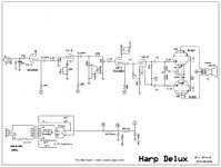
schmatic
ok this is how the amp sits at the moment have a look and see what you think. any suggestions on improvements will be a help. its really nailing the Chicago sound, but I might hav to add a clean Chanel and I'm not sure there is room .might hav to build a bigger one really want to add a re verb tank too
ok this is how the amp sits at the moment
have a look and see what you think. any suggestions on improvements will be a help. its really nailing the Chicago sound, but I might hav to add a clean Chanel and I'm not sure there is room .might hav to build a bigger one really want to add a re verb tank tooAttachments
....higher grid current and device capacitances in the in the 6SL7..............
The "tricks" I applied to convert a 12AX7 circuit (the LPSP) to use 6SL7 were basically just to lower Rg1 values to accommodate the extra grid current,.....
Can you explain, I don't follow.
As I understand it, grid current is almost completely determined by the source impedance and it"s ability to supply current to the grid as it nears 0Vgk and beyond and is only a factor at or near[clipping.
Where did you get specs showing grid current values for 12AX7 and 6SL7?
Last edited:
LPMark,
I'm actually talking about NEGATIVE Grid Current here. That is the current which flows out of the grid and generates a voltage across Rg1 which opposes the bias.
These specs are generally not given but can be inferred from max Rg1 values.
I copy here a post I did some time ago:
Grid Current is one of the most poorly understood topic and so at the risk of teaching grandma to suck eggs I've written a little essay. I posted this to another forum in reply to someomes query but thought I'd copy it here for you possible interest.
Hope its helpful - flag immediately if you think any of it is factually incorrect.
Grid Current and all that – remember that, due to historic limited knowledge, current flow is defined as from positive to negative whereas in actual fact electrons flow from negative to positive.
There are 3 types of grid current
Current flowing into the grid is known as POSITIVE grid current
• When the cathode is heated a cloud of electrons forms around the cathode known as a “space charge”
• Some of these electrons gather at the grid. These electrons then flow out of the grid which is the same as saying that current flows into the grid.
• This positive grid current generates a voltage across the grid leak resistor (Rg1)
• This voltage makes the grid more negative which ADDS to the bias
• If the grid leak resistor is large enough then this positive grid current can generate the entire required bias – This is known as “Grid Leak Bias”
POSITIVE grid current is a low level phenomenon and can easily be overshadowed by NEGATIVE grid current
Current flowing out of the grid is known as NEGATIVE (or REVERSE) grid current
• Negative grid current can be caused by
1. gas ioniszation current
2. leakage current (grid to cathode)
3. grid emission (from grid being heated by the cathode, screen or anode)
• gas ionization current dominates with the other 2 being low level effects
• As electrons accelerate “up” the tube from cathode toward the anode, some of them collide with residual gas atoms. This collision is energetic enough that it strips an outer orbit electron from the gas atom which turns it into a positively charged ion.
• The positively charge ion accelerates back “down” the tube toward the cathode
• Some of these positively charged ions collect at the grid (which is usually the most negative potential of any tube element). Electrons must flow into the grid to neutralize these ions which is the same as saying that current must flow out if the grid
• This current generates a voltage across the grid leak resistor.
• This voltage makes the grid more positive which SUBTRACTS from the bias and results in increase tube current.
• This effect is proportional to tube (anode) current and so is worse in power tubes
• This effect also is worse in old “gassy” tubes.
• This is why there are always 2 specifications for maximum Rg1 values. One value for cathode (auto) bias where the increased current is opposed by an increased bias due to increased voltage drop across the cathode resistor, and another smaller value for fixed bias where there is no action to oppose the current increase.
The mechanism of NEGATIVE grid current, reducing the bias, increasing the current, increasing the negative grid current, reducing the bias etc. etc. round and round, then boom is called thermal run away and is what causes a lot of power tubes to self destruct.
This is made worse by the fact that Rg1 values in most guitar amps ignore the recommended maximum Rg1 values. This is done so as to not load down the output of the phase splitter too much. This is usually compensated to some degree by biasing the output tubes at 70% of rated maximum dissipation, that is, reduce the tube idle current by 30%. That allows use of an Rg1 value of about double the recommended maximum which is based upon running the tube at 100% of its dissipation rating. This helps at idle but does not help much when running the amp with full signal.
So NEGATIVE or REVERSE grid current is something you really need to watch in power tubes.
It can be a problem in small signal tubes as well, particularly high mu triodes which led to the RDH "Rule of Thumb" that for high mu triodes (like 12AX7, 6SL7 etc.) that Rg1 should be no more than 3 times the anode load resistor for cathode bias and no more than twice the anode load resistor for fixed bias.
Those familiar with 12AX7 circuits used in guitar amps will note that Rg1 is often ten times the anode load resistor value. This is because one of the defining characteristics of a 12AX7 which actually makes it ideal in guitar amps is unusually low NEGATIVE grid current.
The above also explains why grid leak bias does not work with older gassy tubes. The negative grid current from the gas ionization opposes the positive grid current needed to establish the grid leak bias.
Grid current is statistical in nature, that is to say that as well as developing a DC voltage across Rg1 it also develops a noise (hiss) voltage across Rg1 which is then amplified by the tube. Low Rg1 values not only give you a more stable bias point but also lower noise. You can think of this as the lower Rg1 shunting the grid noise to ground.
There is one more type of grid current, GRID RECTIFICATION Current. When the grid is taken positive with respect to the cathode the grid to cathode circuit starts to look like a forward biased diode. Current into the grid increases with more positive voltage and usually this has the effect of clamping the positive going signal at the grid. The current also charges up any interstage coupling (DC Blocking) capacitor and this is the root cause of blocking distortion.
Cheers,
Ian
gingertube,
Thank's for that very detailed explanation.
Factually correct, yes.
The form of grid current in question here I have seen referred to as gas current, and as you have stated more of a concern with power tubes and/or high bias current.
I'm not familiar with RDH "rule of thumb" you mentioned, I assume Radio Designers' Handbook? My ignorance.
I looked over nearly a dozen 12AX7 specs and found a rating for Rg max on only one where as it is always listed on power tubes as expected.
I wasn't aware that high mu small signal triodes operated at "reasonable bias levels" with typical values of Rg [<1M] would be subject to bias shift or thermal runaway due to gas current. Bias excursion and blocking due to clipping of course is another matter.
Nice specific reply with good logical arguments and explanations.
- Status
- This old topic is closed. If you want to reopen this topic, contact a moderator using the "Report Post" button.
- Home
- Live Sound
- Instruments and Amps
- ecc83 vs 6sl7 any old tricks?