I am currently building a Carvin Legacy clone.
I have the hi gain preamp channel working, but it's oscillating quite a bit and I am having trouble finding out what is causing it.
The tone controls change the frequency of the oscillation and at certain settings It seems to disappear.
It still oscillates if I pull V1
Moving the b+ wires that go from the powersupply caps to the plates also changes the frequency of the oscillation, but it does not stop it.
The lead 1 channel and the effect loop send are the only things connected at the moment.
I am using a regulated heater supply and my b+ supply is pretty much identical to the schematic.
Any help is greatly appreciated.
The schematic I am using is attached.
Attachments
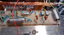
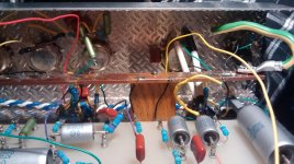
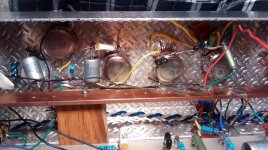
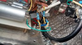
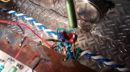
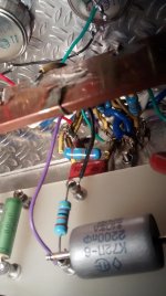
I have a few photos of the preamp board, tube sockets and the tone stack here.
The wiring is less neat than it was before I started my fault finding, and some parts are missing the final insulation as I moved some wires and components and tried shielding some of the wires, so the final wiring should be more neat than it is now.
The plate resistors are wired directly to the tube sockets and to a turret next to the sockets. Cathode resistors and capacitors are also wired to the sockets and go straigh to the buss bar running over them.
I will get some photos of the powersupply tomorrow.
Thanks.
Attachments
Sounds like there is some feedback causing the problem.
Is B+ to the first valves decoupled well ?
There really should be separate decoupling on each stage to stop feedback through the B+.
It is wired like the schematic I posted, so all the preamp stages get power from the last capacitor in the powersupply.
As far as I can see the only decoupling between the preamp stages is from the plate resistor bypass capacitors.
I have not done anything else there because I assumed that I could get it to work the way it is written in the schematic, but I can try to add decoupling and see if it helps.
Thanks.
Did you try swapping the output leads (to make sure the negative feedback connection is correct phase)?
The powerstage and output transformer are not connected, only the lead preamp channel, effect loop send and powersupply is connected at the moment.
Most propably lead dress, bad grounding, bad tube, wrong component and/or lack of decoupling of triode stages.
I would start by disconnecting each triode stages one by one to find out where does the oscillation come from.
Carvin Legacy is high-gain preamp which are not easy to make without oscillation etc. You have got quite a long wires and sorry to say, not good layout!
I would propably start again by putting ALL components to tag board and re-think layout with shortest wires possible. If you need cross wires, cross them at 90 degrees angle.
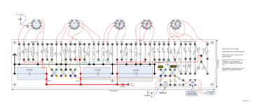
I am attaching you layout of famous very high-gain amplifier. This is how it should be done!
I would start by disconnecting each triode stages one by one to find out where does the oscillation come from.
Carvin Legacy is high-gain preamp which are not easy to make without oscillation etc. You have got quite a long wires and sorry to say, not good layout!
I would propably start again by putting ALL components to tag board and re-think layout with shortest wires possible. If you need cross wires, cross them at 90 degrees angle.
I am attaching you layout of famous very high-gain amplifier. This is how it should be done!
Attachments
Last edited:
I had one but Chinese EL34Bs literally blew up/exploded shot glass out the back side lol...fried all them underrated screen resistors/arced hell out of sockets/ proceeded to melt holes in the pcb....
I don't know bad ground/shielding /bad tube/noisy/ issue with your oscillation?....or maybe add some more grid/stoppers somewhere?
I don't know bad ground/shielding /bad tube/noisy/ issue with your oscillation?....or maybe add some more grid/stoppers somewhere?
Last edited:
Most propably lead dress, bad grounding, bad tube, wrong component and/or lack of decoupling of triode stages.
I would start by disconnecting each triode stages one by one to find out where does the oscillation come from.
Carvin Legacy is high-gain preamp which are not easy to make without oscillation etc. You have got quite a long wires and sorry to say, not good layout!
I would propably start again by putting ALL components to tag board and re-think layout with shortest wires possible. If you need cross wires, cross them at 90 degrees angle.
I am attaching you layout of famous very high-gain amplifier. This is how it should be done!
Thanks for the reply, I have not had time to do any more testing yet, but I have some idea of how to proceed now.
I know it's not a tube, I swapped around a few tubes just to be sure at first and I have gone over the circuit several times to make sure everything is wired correctly and with the right component values.
My longest wires are the b+ wires as I tried to keep the powersupply as far away from the preamp circuit as possible, but perhaps it's a better idea to move the filter capacitors close to the board, or on to the board ?
Ill try disconnecting one stage at a time to narrow down the problem, I should have thought about that before.
You are right, I should probably make a new board once i figure out what the issue is.
I was adviced on another forum before the build to put the tonestack components directly on the pots, and the plate resistors as close to the sockets as possible.
But in retrospect this has made it more difficult to work with and I wish that I had put them all on the turret board to begin with, but I guess it's a learning process, and it's not too late to change things.
The general rules are to keep all leads as short as possible; twist signal wires(or use shielded cable, shield connected to gnd. at one end only) and heater wires; if you must cross signal wires with any others, cross at right angles;proper decoupling in the B+ rail; keep heater wires as far as possible from signal wires.
Thanks for the reply, I have not had time to do any more testing yet, but I have some idea of how to proceed now.
I know it's not a tube, I swapped around a few tubes just to be sure at first and I have gone over the circuit several times to make sure everything is wired correctly and with the right component values.
My longest wires are the b+ wires as I tried to keep the powersupply as far away from the preamp circuit as possible, but perhaps it's a better idea to move the filter capacitors close to the board, or on to the board ?
Ill try disconnecting one stage at a time to narrow down the problem, I should have thought about that before.
You are right, I should probably make a new board once i figure out what the issue is.
I was adviced on another forum before the build to put the tonestack components directly on the pots, and the plate resistors as close to the sockets as possible.
But in retrospect this has made it more difficult to work with and I wish that I had put them all on the turret board to begin with, but I guess it's a learning process, and it's not too late to change things.
I would start over, redo the layout, make proper decoupling of triode stages and it will work fine.
Or....just a thought...get a AMT B1 (or B2) and be amazed
") .
.Looking over the amp once more and poking around a bit when disconnecting individual triodes I found that one of my rectifier diodes are broken, it looked fine, but one of the legs just separated from the body of the diode when i touched it, perhaps I bent the legs a bit too close to the body when installing them and broke it by accident.
The layout certainly has issues, so I can work on a new preamp board while waiting for replacement diodes in the mail, and hopefully it will work well when the new diode is in place and the layout is improved.
Thanks for all your help so far.
The layout certainly has issues, so I can work on a new preamp board while waiting for replacement diodes in the mail, and hopefully it will work well when the new diode is in place and the layout is improved.
Thanks for all your help so far.
Practice Makes Perfect
For some, perhaps most, amp building takes several runs at it to get a finished product you will be happy with. Keep at it and consider how much you've learned from this project. You may have to build it over again and don't hesitate to do so if it doesn't sound right or look good as you'll be happier in the end with something you're satisfied with; and proud of your achievement.
Regarding the broken diode leg- It is unlikely you broke the lead. Parts manufacturing has gotten very price competitive recently and was very much so to start with. I recently had a problem with a resistor that for all appearances looked just fine but it was open when installed. Never had that happen before. The lead would have to been bent back and forth many times to simply break like that... But then I've changed things too enough to just throw out a part after de-soldering and moving for the umpteenth time.
I would be interested in seeing a zoomed out picture of the entire amp also.
Best of luck,
Ccat.
It's not my first amp build, but it's my first venture into hi gain designs, so it is a big learning experience.
It's not completed, so the rest of the amp is not very interesting at the moment, it's mostly an empty chassis exept for the preamp.
The only things that are in there is the preamp that I have uploaded pictures of, a simple lm338 based regulated heater supply , the b+ supply and the ground buss bar.
My plan at the moment is to use EL34s for the power section when that time comes.
- Status
- This old topic is closed. If you want to reopen this topic, contact a moderator using the "Report Post" button.
- Home
- Live Sound
- Instruments and Amps
- Carvin legacy guitar amp build oscillation trouble