At another forum a poster wanted to make a low voltage Marshall amp. He did not know what was involved and when realized he was out of his element he went on to other things. Me, I have spent so much time outside my element I can not really remember what my element is. So of course I thought I would give the low voltage Marshall a try.
I wanted to keep the voltage under 48V, in lot of jurisdictions that is considered a save voltage that you can not really hurt yourself badly. I wanted to use one transformer for the heaters and the power supply so I selected the 25L6 for the output tube which heater needs 25V. The 6AU6 also comes in a 12V version and putting a couple in series would allow a person to run them off the same winding. Another reason for using the 6AU6 is that I won an auction for 50 of the tubes at a low initial bid and have no real application for them.
I took an old chassis that I tried making a 100W SS amp in when I was in my teen's and mounted sockets, transformers, pots and a breadboard
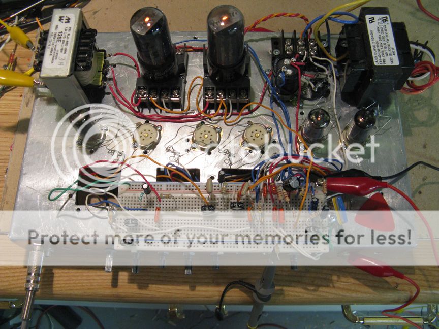
I used a bridge rectifier to get about 34V from the 24V transformer. Threw together a bias circuit for the output tube and did a input stage going to a LTP PI then to the output tubes. I originally thought of using a 70V line matching transformer (for intercom speakers in hospitals, schools, and the like) as a 10W one is suppose to have down to a 500 ohm winding when used in P-P. Putting together the test circuit I used a Hammond multitap transformer I had instead, thought it went down lower but for an 8 ohm load the lowest impedance it has is 3k. Good enough for a start, got the circuit working enough to see if it was worth bothering with.
Well it was pretty much not worth bothering with. Just not enough voltage to get enough volume out of the amp. While I had it set up I decided to try it at 50V. Passable for someone that had an efficient speaker and lived in an apartment block. I thought about using 35C5's which would get the dc voltage up to 50V, then thought what if you used a 12L6 and a voltage trippler? Could also use two 6AU6's in series or a 12AU6 directly across the transformer. See, it is feasible, good enough for me to try the full circuit.
With the test circuit I found to get the most volume out of the 25L6 I had to run the bias voltage around 3V, not a lot of headroom. I also found that the normal method of supplying the screens of the preamp tubes voltage with a resistor off the supply and with a capacitor to ground did not change the operation of the tube much and that I could just connect the screens to the supply. Makes for a lower parts count and complexity. Thought what is good for a preamp tube might be good for a power tube so I ran those off the supply also. Going to be hard getting to the screens dissipation limits running at these voltages. I also thought I could simplify the circuit by going cathode bias on the output tubes. Loosing three volts will not matter much and it lowers the complexity. I did give each tube their own cathode resistor as I wanted to know what each tube was drawing. I have a bunch of used tubes and found some are not all that healthy.
After spending some time getting the circuit to work I came up with the following values.
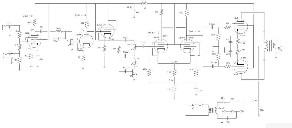
Not a lot of gain as compared to a Marshall but then again we don't have a lot of headroom to work with. I tried a higher plate resistor on the input tube but it sounded a little ratty. I did not have the tone stack working, I think I have a bad treble pot. In place of the stack I put a 1M pot in as a volume control. As little the amount of gain it is easy to overload the PI without any attenuation. Probably will lose the mid pot when I get back to looking at this project and putting in the tone controls.
I wanted to keep the voltage under 48V, in lot of jurisdictions that is considered a save voltage that you can not really hurt yourself badly. I wanted to use one transformer for the heaters and the power supply so I selected the 25L6 for the output tube which heater needs 25V. The 6AU6 also comes in a 12V version and putting a couple in series would allow a person to run them off the same winding. Another reason for using the 6AU6 is that I won an auction for 50 of the tubes at a low initial bid and have no real application for them.
I took an old chassis that I tried making a 100W SS amp in when I was in my teen's and mounted sockets, transformers, pots and a breadboard
I used a bridge rectifier to get about 34V from the 24V transformer. Threw together a bias circuit for the output tube and did a input stage going to a LTP PI then to the output tubes. I originally thought of using a 70V line matching transformer (for intercom speakers in hospitals, schools, and the like) as a 10W one is suppose to have down to a 500 ohm winding when used in P-P. Putting together the test circuit I used a Hammond multitap transformer I had instead, thought it went down lower but for an 8 ohm load the lowest impedance it has is 3k. Good enough for a start, got the circuit working enough to see if it was worth bothering with.
Well it was pretty much not worth bothering with. Just not enough voltage to get enough volume out of the amp. While I had it set up I decided to try it at 50V. Passable for someone that had an efficient speaker and lived in an apartment block. I thought about using 35C5's which would get the dc voltage up to 50V, then thought what if you used a 12L6 and a voltage trippler? Could also use two 6AU6's in series or a 12AU6 directly across the transformer. See, it is feasible, good enough for me to try the full circuit.
With the test circuit I found to get the most volume out of the 25L6 I had to run the bias voltage around 3V, not a lot of headroom. I also found that the normal method of supplying the screens of the preamp tubes voltage with a resistor off the supply and with a capacitor to ground did not change the operation of the tube much and that I could just connect the screens to the supply. Makes for a lower parts count and complexity. Thought what is good for a preamp tube might be good for a power tube so I ran those off the supply also. Going to be hard getting to the screens dissipation limits running at these voltages. I also thought I could simplify the circuit by going cathode bias on the output tubes. Loosing three volts will not matter much and it lowers the complexity. I did give each tube their own cathode resistor as I wanted to know what each tube was drawing. I have a bunch of used tubes and found some are not all that healthy.
After spending some time getting the circuit to work I came up with the following values.
Not a lot of gain as compared to a Marshall but then again we don't have a lot of headroom to work with. I tried a higher plate resistor on the input tube but it sounded a little ratty. I did not have the tone stack working, I think I have a bad treble pot. In place of the stack I put a 1M pot in as a volume control. As little the amount of gain it is easy to overload the PI without any attenuation. Probably will lose the mid pot when I get back to looking at this project and putting in the tone controls.
Nice experimental project.
Interesting screens connections - never thought of that.
With all those tubes you could do same preamp with a pp 6AU6 into a 5w line trafo. With the right voltage you could get maybe 4w out of it - which is still too loud in my apartment block. 🙂
Cheers
JimG
Interesting screens connections - never thought of that.
With all those tubes you could do same preamp with a pp 6AU6 into a 5w line trafo. With the right voltage you could get maybe 4w out of it - which is still too loud in my apartment block. 🙂
Cheers
JimG
I had some trimmers that I used to adjust the resistance between the screens and the power supply. I also hooked up the trimmers across the supply and took the screen voltage off the wiper. I found I got the best performance out of the tubes with the most voltage. From there just hooking up the screens to the supply was a no-brainer. No more reason to use the cap to ground so another part gone.
I am going to try a few simpler circuits along with just volume and tone, at low levels I think simpler is better for tone controls. I would like to come up with a low voltage amp that those who like the idea of building an amp can do but they are weary of the high voltages. Then after they have it running they might take the leap and up the voltage to get more out of the amp (with a few added parts for the screens). By that time we will have got them hooked. 😀
I am going to try a few simpler circuits along with just volume and tone, at low levels I think simpler is better for tone controls. I would like to come up with a low voltage amp that those who like the idea of building an amp can do but they are weary of the high voltages. Then after they have it running they might take the leap and up the voltage to get more out of the amp (with a few added parts for the screens). By that time we will have got them hooked. 😀
I Played with the circuit and stepped through the impedances rather than using the 3K. I got an increase using the 6.8k tap. Measured a clean sine wave and I was getting a whopping 0.25W. It is getting pretty close to practice amp status! Tried again with the 70V transformer, really wanted it to work as it can be gotten cheaply, the real OT works better. Might have to revisit the preamp tubes now.
I'm interested in your project for the same reasons - hooking beginners. A contributor at the watkins.com (tone per buck club) was attempting the same but seems to have lost interest.
I plan to start night classes for beginners with some short form kits powered by back to back 12 volt transformers. Although the voltages are still up in the two hundreds the supplies are very high impedance which contributes another element of safety.
Am I correct thinking your low voltage supply requires lower impedance range seen by the power tubes?
Not quite sure what you mean, guessing either if the power supply is stiff or that the output transformer primary is of low impedance. I found I had more output with the 7.6k primary rather than the 3k.Am I correct thinking your low voltage supply requires lower impedance range seen by the power tubes?
On the PS, the cathode resistors on the outputs are 270 ohms and I am seeing about 3V across them so the idle current is 11 mA. The amp is running Class A so not a big demand on current. The greatest call for current is the heaters.
Hope this is what you want, if not let me know.
Sorry I wasn't clear. I did mean loadline impedance. I was visualising how to get the loadline thro the knee of the pentode curve when the B+ was so low.
But then the screen voltage is low too... Just thinking things through...
But then the screen voltage is low too... Just thinking things through...
Yeah, not a lot to go on as far as low voltage operation. That is why I was hoping some of the bright minds around here might come forward with some words of wisdom. The problem is many of them do not frequent this area of our fishbowl and if you hint at guitar amplifier on the tube /valves area it gets punted to this one.
I did a rough approximation of the load line and thought around 1k might be in order. Surprised when I went to 7.6k from 3k. Shows you how much I know.
I did a rough approximation of the load line and thought around 1k might be in order. Surprised when I went to 7.6k from 3k. Shows you how much I know.
I have an EL91 pp amp on the breadboard, with a VVR circuit in the power supply.
I was surprised at how far down I could take the B+ and still have enough volume for lead guitar in an apartment (like about 50v on the anodes). Only the PA anodes and screens were on the VVR. The preamp tubes' voltages weren't affected.
I figured if the screen voltage came down with the anode voltage then the 0 volt pentode curves came down too to match...
That is what started me on this. I had a separate transformer for the heaters and the HV transformer on a variac. Those horizontal lines on pentode datasheets don't lie. You can get pretty low and still have a listenable amp. Even 1/2 watt can be plenty in mixed company.
Funny to see you here! To find the optimal impedance, you first need to get a general idea of the vgk = 0 curve at your desired screen voltage. You can do this with a couple of multimeters and one static voltage supply and one variable voltage supply (I just use an LM317 fed off my static supply).
You hook up one multimeter as a current meter for the plate current, and the other multimeter to measure the plate voltage, with both cathode and grid grounded. Hook up the static supply to the screen and the variable supply to the plate, and proceed to plot values! Just be aware of your tube dissipation limits.
You actually only need to plot as far as the 'knee' of the curve goes, so once it starts flattening out (when the current no longer significantly increases with plate voltage) you can stop. The general idea is that you want the load line to pass through the knee of the vgk = 0 curve, where maximum power is developed, so you don't really care about the rest of the curves.
Assuming you're running class A you just draw a load line from 2xHT through the knee of the curve and then figure out the impedance, as well as bias current.
Funny to see you here!
Oh oh. (I hate when this happens.) So how is it going? (I still can't remember who this is.) I spent some time here before but now just drop in once in a while. (Maybe it's my brother that he knows and has me confused with him.) ...
I was going to do a plot of the curves but took a short cut and just hooked up the relevant impedances of the output transformer and noted which one gave me the highest power. I do want to go back and do the curves for curiosity sake but at the moment I am in my wood working mode, setting up to make a couple of acoustics. (Maybe I met him in a bar?)
Loadlines are rather useless at low voltages since the curves aren't too accurate and the tube to tube variation is huge.
In theory lower voltage operation would work better with a lower load impedance since you have a limited plate voltage swing. Unfortunately you are also limited by the current that the tube will flow at zero grid volts with your chosen plate and screen voltages.
To get the impedance down you need to get the current up. The easiest way to do this is to drive G1 positive. The easiest way to do that is with a mosfet, but things start to get complicated. Maybe you can find a tube that can pass more current on a low plate voltage.
TV sweep tubes and regulator pass triodes come to mind. I have seen big sweep tubes pass over 1 Amp of current with 50 volts on the plate. The 25BQ6GT will pass 100 mA on 75 volts and probably 75 mA or so on 50 volts. They are on the dollar menu at ESRC. There is a 26 volt version of the venerable 6080, it is the 6082. No problem cranking over 100 mA through these on 26 plate volts, but the heater is rather hungry. Another possibility is the 12B4.
I have been using the 6CW5 and it's odd heater voltage variants (8CW5, 15CW5, 45B5) in audio amps for years. It is similar to the 6BQ5/EL84 except that G2 has a finer winding pitch resulting in higher G2 gain. This means that the tube works on lower voltage than the EL84 and likes a lower load impedance because it can source the current needed to drive it. Back in the Hundred Buck Amp Challenge I was getting 25 watts from a pair of 45B5's on 250 volts with a 3300 ohm load. You can get 25 watts from a pair of EL84's on 6600 ohms but you need almost 400 volts. I have been as low as 135 volts with 45B5's getting over 10 watts with a 2000 ohm load. Maybe they will work on a lower voltage.
Other tubes used in the HBAC for low voltage (135 V) operation were the 60FX5, good but not too cheap, and the 32ET5 lower gain and power out, but $1 or less each.
There was a class of tubes developed for operation with 12 volts on the plate. They are called space charge tubes. There were tube car radios that operated directly on 12 volts in the early 60's, but the power output was rather low. The output stage went to a germanium transistor after only a year or two but the rest remained tube powered for a few years. The 12K5 was one of the output tubes. 50 to 100 mW out on 12 volts, but maybe a watt on 48 V.
The 28D7 was a special dual triode created for use in aircraft on 28 volts a push pull amp using one tube could make 600 mW. I have seen a 12AU7 or 6SN7 do better.
There was a 12 volt guitar amp published on this forum a long time ago. It used a 12U7 which is rated for 30 volts max on the plate. Some speculation says its just a 12AU7 tested to run on 12 volts. The 12SX7 IS a 12SN7 tested to run on 12 volts. None of these will make much power on low voltage without positive grid voltage.
I found this years ago and lost it....Google just lead me back to it.
Space Charge and Other Low-Voltage Tubes
Read the page on Compactron tubes too.
http://www.junkbox.com/electronics/CompactronTubesIndex.shtml
I found the link to the 12 volt guitar amp that used the 12U7
http://www.sophtamps.ca/mambo/index.php?option=com_frontpage&Itemid=1
Space Charge and Other Low-Voltage Tubes
Read the page on Compactron tubes too.
http://www.junkbox.com/electronics/CompactronTubesIndex.shtml
I found the link to the 12 volt guitar amp that used the 12U7
http://www.sophtamps.ca/mambo/index.php?option=com_frontpage&Itemid=1
Last edited:
I looked up a number of tubes that I have, one being the 8CW5, and all the 10-12W tubes have about 50mA around the 50V line. Whether a 8CW5 will swing closer to 0V I can't say. I had the screw terminal octal sockets courtesy of our hundred buck patron so I went with the 25L6.
I have one 25DN6 which would swing more current but getting another one will cost me $15-20 due to shipping and this is just a what-if exercise anyway. I have a couple of 7695 tubes that are audio tubes designed to run at about 130V which would be a good candidate but I wanted to go with a cheaper tube that is more available. The 7695 has 50V heaters which puts me over my under 50V circuit requirement. With a 48V transformer a pair of these would be good for a couple of watts.
I think the big TV tubes are the way to go without positive grid drive.
Hey Mr. tubelab, found you mentioned the 6HB6 in another thread, looks promising. Operation at 60V plate listed (although 150V screen) and passes 150mA.
http://tubedata.milbert.com/sheets/049/6/6HB6.pdf
http://tubedata.milbert.com/sheets/049/6/6HB6.pdf
I like the 6HB6 enough to buy 500 of them (for 35 cents each), but it needs screen voltage to work well. The screen curves are here:
http://www.mif.pg.gda.pl/homepages/frank/sheets/135/6/6HB6.pdf
With 50 volts plate and screen and 0 volts on G1, you only get about 10 mA. The 6HB6 is an EL84 with a fine pitch control grid for high Gm (and a different pinout). The 6CW5 is an EL84 with a fine pitch G2. Too bad they never put both high gain grids in the same tube.
I bought 100 25DN6's too (50 cents each). The guy at Vacuumtubes.net convinced me to buy over 1000 tubes that day, and he did it with price. I needed some 6HJ5's (another good tube, but not too common) and they were $2 if I bought 1000 tubes total. Otherwise they were $5. I would send you a couple 25DN6's, but yes the postage is $20 for $1 worth of tubes🙁
I got a few hundred 6BQ6's too. I got them for an average cost of about 60 cents so I use these cheap tubes and 13GB5's ($1) for screen drive and other experiments that could end badly for the tube.....I have killed a few 6BQ6's and at least two 25DN6's. I haven't killed a 13GB5 yet despite extracting 135 audio watts from a pair for about 2 hours straight. All of these experiments have been at the other end of the voltage spectrum, over 600 volts.
Well the 6HB6 is out then. It is a good thing (or maybe not) that I bought the tubes that I have when I did, a couple years ago shipping was cheaper. I have more than I will ever use in my guitar playing life, it is just these oddball projects where it limits me. In a way maybe that is a good thing. I have less ideas to chase down.
The 6HB6 works pretty good in a 18 watt Marshall inspired circuit. Their extra gain lowers the drive requirements so overdrive is abundant. Bias requirements are far less, maybe 10 to 15 volts negative on the grids. Cathode bias works good. They need voltage. 300 volts is OK more is better. I had a setup running at 420+ plate and 325 screen and it screamed to almost 30 watts into 6600 ohms.
Do tubes run when they see you coming?The 6HB6 works pretty good in a 18 watt Marshall inspired circuit. Their extra gain lowers the drive requirements so overdrive is abundant. Bias requirements are far less, maybe 10 to 15 volts negative on the grids. Cathode bias works good. They need voltage. 300 volts is OK more is better. I had a setup running at 420+ plate and 325 screen and it screamed to almost 30 watts into 6600 ohms.
- Status
- Not open for further replies.
- Home
- Live Sound
- Instruments and Amps
- Low voltage Marshall inspired amp for voltage challenged individuals.