I have revised my plans to make a less complicated first amp project. I've been trying to get the parts together for a 5f1 champ but there are certain parts that i do not have. I would like to make substitutions for those parts but i'd like to discuss things first.
1. I've got a good pt with a center-tapped 800v secondary (and i only need half of that, right?), then a pretty beefy silicon bridge rectifier. The situation with filter caps isn't as good. I do have one multi-tap cannister with 30uf, 20uf and 4uf. I have another cannister that has 4/4/4/4. I also have some very large (in terms of physical size - and therefore might not fit in the case i'd like to use) caps that have ratings between 22 and 68 uf.
2. While on the topic of caps - i have some silver mica coupling caps rated at .033uF. This is a higher value than Fender uses (.022uF) but my research suggested that it would be fine. I would like to hear opinions about that if possible. I also have 2 large-ish .1uf silver mica caps available. Too big? I notice hifi systems use bigger coupling caps but guitar amps seem to be on the small side.
3. Volume pot: schematic calls for 1m. I've got a 2m, two 500k and a bunch of smaller values. What would be the effect of a bigger or smaller pot? I was thinking it might be a good idea to just buy the right pot but i'd love to understand why the pot is sized at 1 meg.
4. I think that i will be able to understand the biasing for the most part, but there seems to be quite a range of values that will work. That probably should make me feel better but it's actually stressing me out. I want to be conservative at first. I don't have any 6v6 tubes but I do have a few 6l6 tubes. A 6L6 can handle more power than a 6v6, so would it be fine to use the exact values listed in the champ schematic?
In other words i would bias the amp for 6v6, but install 6l6 tubes.
I'm not too worried about how it will sound right now. Once I have a working amp I can go in and figure out how to be more precise with my biasing and maybe add some tone-shaping and a negative feedback circuit. I just want to get started and i want to be certain that i'm not damaging any components.
Here is a link to the schematic for reference:
http://www.davidsonamp.com/sf/images/champ5f1.gif
I would really appreciate any help.
If your transformer is 800 ct using a bridge rectifier your output voltage will be 400x1.414= 565 volts! VERY toasty tubes..
Fender usually used 660 vct with 5y3 rectifier which yield about 350 B+.
If using SS use a 550 volt ct transformer.
just use in4007 diodes in a full wave configuration.
Fender usually used 660 vct with 5y3 rectifier which yield about 350 B+.
If using SS use a 550 volt ct transformer.
just use in4007 diodes in a full wave configuration.
If your transformer is 800 ct using a bridge rectifier your output voltage will be 400x1.414= 565 volts! VERY toasty tubes..
Fender usually used 660 vct with 5y3 rectifier which yield about 350 B+.
If using SS use a 550 volt ct transformer.
just use in4007 diodes in a full wave configuration.
I thought that i would just use half of the secondary - 400vac, which - and i may be mistaken so please correct me if i'm wrong - should work out to about .9vrms = 360vdc or so.
Full Wave Rectifier and Bridge Rectifier Theory
But i haven't thought about any of this since i went to school in 1999 so i have a low level of confidence in myself. Am i misunderstanding?
My understanding of this is slightly better than yours. I just started in tube about two years ago. Math is very rusty after high school 40 years ago.
If using a half wave your voltage will be .9 of the original. using a bridge will be 1.4 times the original.
this voltage can be adjusted somewhat by playing around withe first capacitor of your filter circuit.
I find this a VERY useful for figuring out a power supply Download
If using a half wave your voltage will be .9 of the original. using a bridge will be 1.4 times the original.
this voltage can be adjusted somewhat by playing around withe first capacitor of your filter circuit.
I find this a VERY useful for figuring out a power supply Download
Your power transformer is just not appropriate, the voltage is way too high. Champ clone transformers are not expensive.
When that original Champ came out, caps were expensive. That is why they used small values like 8uf. Today I would use 20uf or 22uf and not look back.
If you have a can can with 4-4-4-4uf sections, I have to ask, how OLD is it? If it is from the 1950s or 1960s, it is ancient, and I wouldn;t use it, any more than I would trust 60 year old tires I found in my garage. The most common restorative thing we have to do to old amps is replace all their caps.
0.03uf instead of 0.02uf? In this amp you probably get away with it. In general, you are toying with the tone structure of the amp.
This is a guitar amp, not a NASA space probe, the values are not critical at all. You can use a 2meg or 500k for a volume pot if you like. Someone may calculate some small tonal difference, but really, it will sound like a Champ either way.
While it is critical that tubes be biased, the amount of it is not critical. On the one end, you don;t want the tubes running so hot they get red hot, or on the other end you don;t want them so cold they sound asleep or super distorted. Between those limits, there is no "wrong." Bias is not something you need to hide in the closet and quake in fear over. Always remember, it is just a guitar amp.
6V6 and 6L6 are different tubes. Yes, they have the same base and will function in each other's sockets. But their needs are different, and at your level, I would just work with the tube the amp was designed for and not think a 6L6 was just a real heavy duty 6V6.
Or just build a single ended 6L6 amp in the first place.
I feel like I need to apologize - I am not communicating very well. I was mistaken - I thought that I understood the process well enough to start drawing up a schematic. I can see now that I still need to learn some theory.
Since I've confused matters I feel that it may be beneficial to me if I structure my plans - and I will share that outline here so that I can (hopefully) start asking better questions in the future.
I. Goals and PreferencesII. Assets
Perhaps I could use the 12bh7a as the power stage? Maybe I could do half-wave rectification of my 400V secondary and bias my tubes cold? I ought to be able to get 250-300 volts or so?
Since I've confused matters I feel that it may be beneficial to me if I structure my plans - and I will share that outline here so that I can (hopefully) start asking better questions in the future.
I. Goals and Preferences
A. Primary Goal
1. Build functioning tube amp head
B. Secondary Goals (goals that I'd prefer to keep if possible)
1. Build amp entirely out of scavenged parts. (to save money, but also for pride)
2. Build an amp that I can upgrade later.
C. Preferences2. Build an amp that I can upgrade later.
1. Cathode bias
2. Single-ended
3. Watts - whatever works. If I end up with 12 watts, that's fine. (assuming that it's a design that I can modify for lower output) Conversely, if I end up with 1/4 watt that's fine too. (assuming I can upgrade it later, of course)
2. Single-ended
3. Watts - whatever works. If I end up with 12 watts, that's fine. (assuming that it's a design that I can modify for lower output) Conversely, if I end up with 1/4 watt that's fine too. (assuming I can upgrade it later, of course)
A. IronB. Tubes (known useful tubes toward the top, tubes that seem unlikely to be of use to me toward the bottom. I still haven't researched them all yet...)
III. Conclusion1. Power Transformers
a. Scavenged PT with 400-0-400 secondary. Bigger than I need.
b. A wide assortment of used step-down transformers in various sizes, but none that provide 6.3 volts for the heater.
c. An unknown PT from an old (8-track) solid state receiver that does have 6.3 and 12 volt outputs, but I can't figure out what it's rated.
2. Output Transformersb. A wide assortment of used step-down transformers in various sizes, but none that provide 6.3 volts for the heater.
c. An unknown PT from an old (8-track) solid state receiver that does have 6.3 and 12 volt outputs, but I can't figure out what it's rated.
I have an OT from a Bogen CHA 33 chassis that appears to be suitable for my needs. ~ 4.6k Zout @ 8 ohm tap. Should be suitable for 6l6, 6v6 (if I break my second goal and purchase one) and 12bh7a
4x: 12ax7
10+: 12au7 (best selection)
6x: 6bg6
2x: 6L6
5x of 7867 tubes
10+: 5u4gb
3x: 3B28
2x: 12bh7a
1x of OD 3
1x: 5751
1x: oa4g
3x: 12sn7
3x: 12sl7
3x: 12h6
1x: 6av6
1x: 6x4
2x: 12sn7gta
1x: 6sn7gtb
4x: 115n045
3x: ob2
11x: od3
2x: 6cd6ga
2x: 6aq5a
1x: 6x5gt
C: Caps10+: 12au7 (best selection)
6x: 6bg6
2x: 6L6
5x of 7867 tubes
10+: 5u4gb
3x: 3B28
2x: 12bh7a
1x of OD 3
1x: 5751
1x: oa4g
3x: 12sn7
3x: 12sl7
3x: 12h6
1x: 6av6
1x: 6x4
2x: 12sn7gta
1x: 6sn7gtb
4x: 115n045
3x: ob2
11x: od3
2x: 6cd6ga
2x: 6aq5a
1x: 6x5gt
The can cap that I wanted to use made some arcing sounds today when I applied juice to it, so I'm not going to be able to use that. That was the likeliest candidate of the can caps too which leaves me just a handful of ridiculously oversized capacitors from high-bay lighting ballasts and a wide assortment of salvaged low-voltage caps.
The capacitor situation is looking pretty bad.
D: RectifiersThe capacitor situation is looking pretty bad.
1. Silicon Bridge Rectifiers
2. Individual Diodes (build a half-wave rectifier?)
3. Assortment of different tubes (5u4gb) (I would prefer not to use a tube rectifier)
E: Resistors2. Individual Diodes (build a half-wave rectifier?)
3. Assortment of different tubes (5u4gb) (I would prefer not to use a tube rectifier)
Tons of scavenged resistors of various sizes and power ratings. I'm not positive that I have exactly what I need (until I figure out biasing) but I think it's likely that I'll be able to come up with the right parts
F: Potentiometers
1. 2 Meg tone pot (from CHA-33 PA) with integrated on/off switch
2. 500k (linear? Not sure about any of these actually)
3. 50k
4. 5k
5. 1k
G: Miscellaneous Other2. 500k (linear? Not sure about any of these actually)
3. 50k
4. 5k
5. 1k
1. 1/4 input jacks
2. Grounded power cord
3. Tons of chassis material and - worst case - a co-worker who will help me make anything I want on the lathe.
4. Cool metal space-heater case that I stripped out.
5. Wires of all sorts
6. Heat-sinks
7. RCA jacks
8. Terminal Strips of all sizes
9. Switches
10. Fuses
11. Relays
12. Contactors
I want to get something working first. I care how it sounds - I'd like it to be superior to the 20 dollar solid-state amp that I've been using at least - but I don't need sonic bliss. I'm not going to be too picky. No motorboating. No farty, terrible sounding breakup. No weird feedback problems.
Once I've got a working amp then I'll have a reference point and I'll be able to make better choices when I start to make upgrades. If you read the whole outline then you're a saint. Thank you for reading.
I'm guessing that I'll need to purchase capacitors. I might need to purchase a PT too I guess. (That would feel like surrender.)Once I've got a working amp then I'll have a reference point and I'll be able to make better choices when I start to make upgrades. If you read the whole outline then you're a saint. Thank you for reading.
Perhaps I could use the 12bh7a as the power stage? Maybe I could do half-wave rectification of my 400V secondary and bias my tubes cold? I ought to be able to get 250-300 volts or so?
Last edited:
And here's my $.02.
Since you like to scrounge like me, I find the best sources for parts from old stereo consoles of yesteryear. Look for them in your local kijiji site. I usually get me for $50 and that comes with everything you need to build an amp. Some are single ended, some are push/pull and usually still works.you may need to buy new caps though as most of the caps in these are on the "tired" side. But, the iron is good. Just make sure they're the tube type. Some of them are built into top grade furniture like Teak and some other exotic woods. Just make sure they're the tube type, as the solid state ones look similar. Usually, if they were made in the '50s or '60s, they'll be tube.
Since you like to scrounge like me, I find the best sources for parts from old stereo consoles of yesteryear. Look for them in your local kijiji site. I usually get me for $50 and that comes with everything you need to build an amp. Some are single ended, some are push/pull and usually still works.you may need to buy new caps though as most of the caps in these are on the "tired" side. But, the iron is good. Just make sure they're the tube type. Some of them are built into top grade furniture like Teak and some other exotic woods. Just make sure they're the tube type, as the solid state ones look similar. Usually, if they were made in the '50s or '60s, they'll be tube.
My $.02
Your transformers which are the majority of the price to build a tube amp is telling you to make a 6L6 PP amplifier. Plus you have the tubes already.
Probably the best advice anyone could give me right there - but I keep thinking about other stuff instead...
And here's my $.02.
Since you like to scrounge like me, I find the best sources for parts from old stereo consoles of yesteryear. Look for them in your local kijiji site. I usually get me for $50 and that comes with everything you need to build an amp. Some are single ended, some are push/pull and usually still works.you may need to buy new caps though as most of the caps in these are on the "tired" side. But, the iron is good. Just make sure they're the tube type. Some of them are built into top grade furniture like Teak and some other exotic woods. Just make sure they're the tube type, as the solid state ones look similar. Usually, if they were made in the '50s or '60s, they'll be tube.
I have to admit that if I were willing to take the easy way out - I now have 3 ancient PA amps to choose from. None of them were working but I can't imagine that it would be anywhere near as difficult to repair them as it is for me to figure out how to turn these parts into a champ.
The first is from the 50s - it uses 4 7867 power tubes. Supposedly a pretty nice mono-block from back in the day.
The other two are both CHA-33 Bogen PA amps. The more beat-up of the 2 has been completely stripped and the other one has a failed PT, and might just need caps and tubes aside from that.
But I think that I wouldn't get satisfaction out of this if I simply repair one of these - and they're way too loud for me anyways. A push-pull 6l6 design would be too loud for me to ever use.
So here's another shot:
The Firefly?
http://ax84.com/media/ax84_m276.gif
If I'm not terribly mistaken I should be able to sub 12bh7a for the 12au7 in the output stage, and have reasonable impedance matching on the transformer I was hoping to use.
Last edited:
Edit button disabled after a certain amount of time?
I finally found data - it shows the OT as having a 6000 ohm center-tap impedance on the primary and it has secondary windings (apparently - from my other thread) for 2, 4, 8, 16, 70V and 600 ohm.
Doesn't match the transformer that's in the schematic though - so I wonder if it was replaced at some point? It did match up when I applied voltage and did some math. I think my figures are probably correct.
Well I am sure you know already that you do not have an air gapped output transformer intended for single ended use. If you really want a champ style amp there are some issues your going to have to address.
First is the output section. You can just use two 6L6's if you don't mind wasting one, just don't use a phase inverter as a driver therefore your only using one output tube. Another way to offset the DC current is to use a current source on one side of the OT, this will be better than wasting a tube but your going to have to scrounge up some SS parts.
Well biasing is going to be an issue because you have such high B+. You need the output valve to conduct throughout the entire 360 degre input signal without exceeding max plate dissipation. I simulated a 5k load (100mA) with your PT and I got 530vdc.
A side note here so bare with me, A champ which is biased at max plate dissipation (18.5/470=39mA minus about 5mA for the screen is 34mA .034x340=11.56) of 12 watts has it's grid referenced to ground and cathode at 18.5 volts, so the grid is -18.5 compared to cathode.
Now a 6L6 biased at max plate dissipation at 530v (if the tube handles it) would be around 34mA .034*520=17.68 watts. Looking at the tube datasheet plate characteristic graph you will see it is no where near center bias, in fact a 10v input signal to grid would put the tube into cut-off. So we need to change bias point and bring voltage down.
So the easiest option is placing some large resistors in series with the HV secondaries going to diodes. I simulated this with a 5k (100mA) load and 100 ohm resistors in series with HV secondaries and it should drop you down to 460v. This is close to the Fender "champ 12" amplifier which uses a 6L6. The Champ 12 uses a voltage divider at the cathode to set the bias but you don't have to. We want a bias current of 44mA which is about -17v grid to cathode. So you could just use a 390k cathode resistor and reference the grid to ground.
Last edited:
Well I am sure you know already that you do not have an air gapped output transformer intended for single ended use. If you really want a champ style amp there are some issues your going to have to address.
First is the output section. You can just use two 6L6's if you don't mind wasting one, just don't use a phase inverter as a driver therefore your only using one output tube. Another way to offset the DC current is to use a current source on one side of the OT, this will be better than wasting a tube but your going to have to scrounge up some SS parts.
Well biasing is going to be an issue because you have such high B+. You need the output valve to conduct throughout the entire 360 degre input signal without exceeding max plate dissipation. I simulated a 5k load (100mA) with your PT and I got 530vdc.
A side note here so bare with me, A champ which is biased at max plate dissipation (18.5/470=39mA minus about 5mA for the screen is 34mA .034x340=11.56) of 12 watts has it's grid referenced to ground and cathode at 18.5 volts, so the grid is -18.5 compared to cathode.
Now a 6L6 biased at max plate dissipation at 530v (if the tube handles it) would be around 34mA .034*520=17.68 watts. Looking at the tube datasheet plate characteristic graph you will see it is no where near center bias, in fact a 10v input signal to grid would put the tube into cut-off. So we need to change bias point and bring voltage down.
So the easiest option is placing some large resistors in series with the HV secondaries going to diodes. I simulated this with a 5k (100mA) load and 100 ohm resistors in series with HV secondaries and it should drop you down to 460v. This is close to the Fender "champ 12" amplifier which uses a 6L6. The Champ 12 uses a voltage divider at the cathode to set the bias but you don't have to. We want a bias current of 44mA which is about -17v grid to cathode. So you could just use a 390k cathode resistor and reference the grid to ground.
That was the greatest.
I admit that I did not know about the air-gapped transformer thing until 2 days ago. I was under the impression that any transformer that had the right impedance matching and power handling characteristics would be fine, but then I noticed that Hammond splits their OTs between single-ended and push-pull. It gave me a sinking feeling.
Then I got frustrated with trying to figure out bias for my super high plate voltages. I was trying to figure out how to reduce B+ as well, but it never occurred to me to place a separate resistor on every plate as you suggested. I assume that it would reduce the effects of the sag problem that I was reading about?
In the meantime I have been exploring lower voltage designs that I might be able to use with another - much smaller PT that I had been considering. With this other transformer I can get a plate voltage of about 325. If I'm understanding the tube data sheets properly I should be able to bias some 6l6 tubes with a plate voltage in that range.
In the meantime I went ahead and did some work on my case. I got 3 switches and a power indicator light in place and I got the fuse and the cord hooked up. It;s not too interesting to talk about but it encouraged me at least. I needed a small victory and I got one.
Maybe I wasn't clear enough on my ideas so I took some time to draw them up for you. A picture is worth a thousand words.
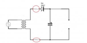
First pic is of a half wave rectifier model where I was speaking about putting the 10 watt 100R resistors to drop your voltage down. This amp is going to be class A so the resistors will not have any "sag" effect on the power supply, they will just reduce B+.
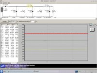
Next pic is of a simulated power supply. The 90mA current tap is to the center tap of output transformer. The 10mA is for the screens, and the 2mA is for the preamp tube. If you are only going to use one power tube the the second current tap will only be 5mA. And depending on if you offset the DC in the primary of OT or not the 90mA will be 45mA.
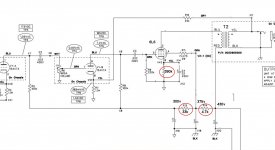
The next pic is of a champ schematic where I highlighted in red the resistor changes to drop your node voltages down. Make a note that you are using a PP OT so you will be putting the B+ to the center tap of the OT. If you are not using a tube to simulate a load on the other half of the primary than you will have to use a large 10k 20watt resistor or a current sink. Or if you don't care about the standing DC current and plan to not even hook up the other half of the primary than change the 4.7k resistor to 15k.
First pic is of a half wave rectifier model where I was speaking about putting the 10 watt 100R resistors to drop your voltage down. This amp is going to be class A so the resistors will not have any "sag" effect on the power supply, they will just reduce B+.
Next pic is of a simulated power supply. The 90mA current tap is to the center tap of output transformer. The 10mA is for the screens, and the 2mA is for the preamp tube. If you are only going to use one power tube the the second current tap will only be 5mA. And depending on if you offset the DC in the primary of OT or not the 90mA will be 45mA.
The next pic is of a champ schematic where I highlighted in red the resistor changes to drop your node voltages down. Make a note that you are using a PP OT so you will be putting the B+ to the center tap of the OT. If you are not using a tube to simulate a load on the other half of the primary than you will have to use a large 10k 20watt resistor or a current sink. Or if you don't care about the standing DC current and plan to not even hook up the other half of the primary than change the 4.7k resistor to 15k.
Attachments
Last edited:
- Status
- This old topic is closed. If you want to reopen this topic, contact a moderator using the "Report Post" button.
- Home
- Live Sound
- Instruments and Amps
- i have a few questions about 5f1 champ project.