Please can some good folk help me cure a hum problem? I have built two Mullard 3+3 valve amplifiers which work very well except that both have rather more hum than I feel they ought. It isn't over powering but certainly a slight distraction during quieter passages of music.
I have used best quality components and the filament wires have been twisted and led round the periphery of the chassis. Each amp hums about the same amount and does so with no input. Turning up the volume control does not increase the amount of hum.
Earthing is largely by bus bar technique except in the early stage where a couple of earth links are made by connections in series and then to the bus bar.
There is only one chassis-earth connection at the RCA input socket end (of course there is a mains earth at the mains input socket at the other end link directly to the bus bar.
I have tried earthing the mains transformer to the bus bar but the hum got worse. I also tried earthing the body of the volume control but that made no difference.
The original Mullard circuit had a resistor and capacitor in the power supply part of the circuit to drive a valve preamp(R16 & C10). I omitted these but I'm wondering if I need to install extra smoothing by implementing this part of the circuit.
I'd be grateful for any suggestions as to possible cures for this hum problem. I should say I have limited theoretical knowledge but am keen to learn
Attachments
Mains earth should go to the chassis, not the ground bus. The ground bus must have one and only one connection to the chassis - you have chosen to do this at the input sockets, which should be fine.xtaljo said:There is only one chassis-earth connection at the RCA input socket end (of course there is a mains earth at the mains input socket at the other end link directly to the bus bar.
How is the mains transformer HT secondary CT grounded? It should go straight to the negative end of C9, then from there to the ground bus. This keeps charging pulses away from the signal ground.
Are you using modern or NOS valves, especially for the EF86? Some modern valves don't have such good heater-cathode insulation, as they assume that DC heaters will be used for low-level circuitry.
Thanks guys.
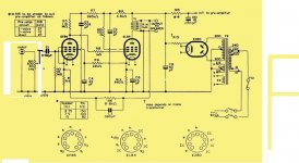
In connecting one end of the ground bus to earth I was following the wiring diagrams given in two articles on constructing this amplifier. I have attached one of these diagrams. However, I am quite happy to try re-wiring the earth to the chassis and disconnecting it from the ground bus. I know certain wiring practices have changed over the years and this looks like one of them. I will report back.
I will also double check the wiring of the CT of the HT secondary.
The valves are from fairly reputable stockists in the UK who say they carry out a range of tests before sending the valves out. As it happens I used two different supplies for the two amps so to lessen the chance of getting valve specific faults. They are a mixtture of 'Mullard' ,'Valvo' and 'Phillips'.
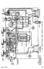
Attachments
Here is a report on what I have done so far:
1) Disconnected mains earth from the Power Supply end of the bus bar. Connected earth terminal of mains socket to the chassis about 1/2" away having cleaned the area and using tightening washers and well well tightened nut. Result: no difference in the level of hum. Hum now increases slightly when volume pot is turned up.
2)Checked that wire from CT of HT secondary winding goes straight to negative side of C9. Initially it went to the bus bar about 2" away but I re-wired it.
Result: no difference in hum level.
3) Tried using different valves, in particular EL84. Swapped 'Mullard' for 'Phillips' and a cryo-treated version supplied by Watford Valves Ltd. Result no significant reduction in hum level.
4) Tried disconnecting earth from body of volume pot. Result slight increase in hum. Connected body of pot. to the junction of the bus bar and the negative side of C9. Result a very slight reduction in hum.
5) Separated some of the wiring around the valve holders particularly around the heater wiring. Care was taken to ensure that the majority of wires ran at right angles to the heater wiring. Just one or two have very short runs parallel to the heater wiring. I'm wondering if the HT wires from the HT secondary winding of the PT which run to thr rectifier anodes ought to be twisted too. At present they run parallel too each other and are separated by about an inch.
6) I have followed Mullard's recommendations about the layout of these amps. So, for example ,the axes of the transformers are at right angles to each other and the input socket is at the EF86 end of the amp etc.
Puzzled I eagerly await any suggestions.
It won't do any harm, and it might help.I'm wondering if the HT wires from the HT secondary winding of the PT which run to thr rectifier anodes ought to be twisted too.
One thing to bear in mind is that back in the 1950s a little hum was regarded as normal. Amplifier input sensitivities were generally much higher than today.
Is the hum 50Hz or 100Hz? Could it be a hum loop created by the source? You said that the hum persists with no input; was this with the input connected but not playing, or input disconnected?
Do you use screened cable for all audio connections at the input? Do you have tone controls (as shown in the wiring diagram) or not (as shown in the circuit diagram)?
What value did you use for C1 0.02uF? Is it a physically large 'audiophile' component? There is a weakness at this point in the circuit. The grid circuit of V1 uses a 10M resistor to provide grid leak bias, so there is a high impedance here. This would be prone to hum pickup via stray capacitance, but C1 imposes a smaller AC impedance - about 160k at 50Hz. This is still quite high so hum pickup could still be a problem, and the physical size of C1 can increase pickup. You need to be very careful with positioning of wires and components at this point.
A modern circuit would use a larger value for C1 and a smaller value for the volume pot so the grid impedance seen by hum would be much smaller, as well as less sensitivity.
This is a single ended amp, there will be no cancellation of hum via push pull stages. The power amp stage here runs directly off the filtered output of the rectifier. It is very dificult in one stage to totally eliminate ripple from the supply. You need not add that branch off to an imaginary preamp, however, if you added another filter stage for this amp, I wager it would help.
Between the top of C9 and the top of T1, add a series choke (or resistance), and add another filter cap (20uf-50uf) to ground from the top of T1. Doing that will be more effective than simply adding 50uf in parallel with C9. In other words, the T1 draws from the first B+ node now, I propose adding a node so T1 draws from the second node, the original first node is still there but no point in the circuit draws directly from it.
In guitar amps we face the fact that single ended simple amps will hum a little. Fender even sent out a service bulletin once telling us the background hum in their Champ amps (single ended) was normal, and we should not try to "repair" it at our warranty service centers.
Many thanks DF96 & Enzo.
I will try twisted HT leads to the EZ80 anodes.
But I have a huntch the hum originates at the input stage as you suggest. It is present even when no input is connected. However, if it started at the input stage wouldn't it increase by turning up the volume. It does slightly but not by that much.
I used 0.02uF for C1 and it is fairly large - about 12mm Diam. X 12mm L . I will try changing the layout of components at this stage as you suggest. I only used screened cable between the input socket centre terminal and the volume control (there are no tone controls on my version). The screening is connected to ground at the input socket end only where the ground is secured to the chassis. Should I use screened cable elsewhere at this stage? Are you suggesting I try different values for C1 (and smaller caps)?
The hum is, I think, largely 50Hz but I think I can also hear a higher frequency to. The latter reduces if I ground the volume pot. body.
Enzo:
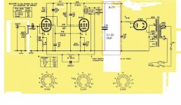
I'm not entirely sure about the circuit mod. you are proposing. I will attach a diagram of what I think you mean and send it in a new msg. Sorry to be rather slow on the uptake.
I really appreciate the help I'm getting and I'm learning a lot too.
I will try twisted HT leads to the EZ80 anodes.
But I have a huntch the hum originates at the input stage as you suggest. It is present even when no input is connected. However, if it started at the input stage wouldn't it increase by turning up the volume. It does slightly but not by that much.
I used 0.02uF for C1 and it is fairly large - about 12mm Diam. X 12mm L . I will try changing the layout of components at this stage as you suggest. I only used screened cable between the input socket centre terminal and the volume control (there are no tone controls on my version). The screening is connected to ground at the input socket end only where the ground is secured to the chassis. Should I use screened cable elsewhere at this stage? Are you suggesting I try different values for C1 (and smaller caps)?
The hum is, I think, largely 50Hz but I think I can also hear a higher frequency to. The latter reduces if I ground the volume pot. body.
Enzo:
I'm not entirely sure about the circuit mod. you are proposing. I will attach a diagram of what I think you mean and send it in a new msg. Sorry to be rather slow on the uptake.
I really appreciate the help I'm getting and I'm learning a lot too.
Yes, that is exactly what I was proposing. The R? could also be a choke.
COmpare these Fender Champ power supplies which are done as my suggestion:
http://www.webphix.com/schematic heaven/www.schematicheaven.com/fenderamps/champ_5e1_schem.pdf
http://www.webphix.com/schematic heaven/www.schematicheaven.com/fenderamps/champ_5c1_schem.pdf
To this later one, whwich is done as your original cicuit, and is noisier:
http://www.webphix.com/schematic heaven/www.schematicheaven.com/fenderamps/champ_5f1_schem.pdf
In the later version, Fender decided to save a couple dollars, the increase in hum being considered "good enough."
SOmething else to consider: hum is not generic, it can come from multiple sources and each source has its own remedy. So you may have some B+ ripple hum, which my extra filter may help, but you may ALSO have hum from tube heaters, or from grounding issues, or from insufficient shielding, or whatever. So if you have a small amount of hum in the first stage, the volume control might reduce ity, or pulling the preamp tube might reduce it, but those things won;t affect hum in the power tube stage. That might explain the volume control helping a small amount but not completely.
R? is not critical, without calculating anything, I'd think 250-500 ohms would be a place to start. A small choke would be appropriate. Antique Electronic Supply LLC offers a selection. I'd probably start with a resistor to see if the arrangement helps. Then if I felt the NEED for a choke, I;d check the B+ current draw of the whole circuit and check my choices based upon that.
It is just an idea, you might find just slapping larger filters in the existing circuit to be enough.
100Hz hum is from power supply ripple, and that is what my idea fights. 50Hz hum is from grounding, shielding, radiated pickup of transformer field, heater noise. 100Hz and 50Hz are the same note musically, one is an octave higher.
Did you try the 100 ohm resistors from each side of the heater supply to ground? Measure each side of the heater supply to ground. Reading of 50 to 100VAC are not uncommon. This large voltage is caused by capacitance within the transformer between the heater winding and one end of the high voltage winding. The 100 ohm resistors (called a virtual center tap) short this voltage to ground.
One way to eliminate the heater supply as the cause is to disconnect both sides from the transformer and connect a battery or other DC power supply.
One way to eliminate the heater supply as the cause is to disconnect both sides from the transformer and connect a battery or other DC power supply.
Thanks everyone. Hum cured!!!
I was re-arranging the components at the input stage and this improved things somewhat. Then I noticed I had wired an unnecessary/duplicate ground connection to the bus bar causing a ground loop. One snip (amp off) and (amp on) all was well! Just a slight residual hum if you put your ear within a couple of inches of the speaker which is normal.
I'm so grateful. There is so much useful information in this thread I'm going to save it for future projects. Sorry it was partly my error.
The Mullard 3+3s sound great now, just as I hoped they would.
Thanks again guys.
- Status
- This old topic is closed. If you want to reopen this topic, contact a moderator using the "Report Post" button.
- Home
- Live Sound
- Instruments and Amps
- Curing hum in Mullard 3+3 valve amplifiers