Hi,
First post in this forum so hello to you all.
A couple of month ago I decided to build and experiment with a tube based fuzz .
I read numerous articles on tube theory and looked at hundreds of schematics.
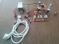
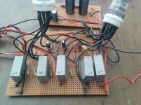
Yesterday I finished building my first working prototype.
Goals:
-High plate voltage. Not like the starved plate designs I found around the net.
-Use the low price soviet 6n2p-ev
-Add a single POT tone stack - the muff design was chosen
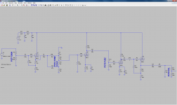
The design uses two 6n2p-ev dual triodes. A cathode follower as an input two gain stages and another CF at the output.
I do have a problem with the tone stack that will need to be fixed...when I shift the pot towards the bass, the signal gets really weird. Maybe I am loading the input stage CF ???
I attached my design schematics and a link to a short clip I took showing the output of the fuzz with a 1kHz 100mVp-p input.
Your wise comments are appreciated!
DIY tube based fuzz - YouTube
S.B.D
First post in this forum so hello to you all.
A couple of month ago I decided to build and experiment with a tube based fuzz .
I read numerous articles on tube theory and looked at hundreds of schematics.
Yesterday I finished building my first working prototype.
Goals:
-High plate voltage. Not like the starved plate designs I found around the net.
-Use the low price soviet 6n2p-ev
-Add a single POT tone stack - the muff design was chosen
The design uses two 6n2p-ev dual triodes. A cathode follower as an input two gain stages and another CF at the output.
I do have a problem with the tone stack that will need to be fixed...when I shift the pot towards the bass, the signal gets really weird. Maybe I am loading the input stage CF ???
I attached my design schematics and a link to a short clip I took showing the output of the fuzz with a 1kHz 100mVp-p input.
Your wise comments are appreciated!
DIY tube based fuzz - YouTube

S.B.D
Cool. Did you try it with the tone stack after the distorting tubes? Too much bass going into the distorting tubes doesn't give me good results. (There is no reason not to have tone before AND after your sound generating tubes either). Keep us up to date.
Regards & welcome.
JimG
Regards & welcome.
JimG
Hi,
Thanks for the help and comments. This is what I came up with today.
With the input floating I see 50Hz oscillation and the tone stack interacts with these oscillation - chopping and messing with it to form a weird signal that measures around 1.5khz on the scope. I earthed the secondary side of the transformer (negative rail), this helped a bit... now the tone stack does not seem to destroy the signal coming out of the function generator, but still I see the 50Hz oscillations when the input floats. When the function generator is connected with the output disabled I don't see the 50Hz noise.
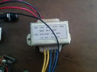
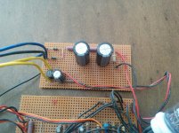
What is the most likely source of the 50Hz? The heater supply rail or B+ voltage rail? I have only a single 1000uF cap after the diode bridge on the 6.3V heater transformer output (I have seen designs with 6000uF on the heater supply).
Also, did I make a mistake by connecting the heater negative supply and the B+ negative rail together?
Tomorrow I will change the tone stack 100k pot to a 500k pot. According to the LTspice simulation, it is loading the higher frequencies and does not get them to clip over 6-7khz. I verified this with the function generator and scope (nice to see that the spice model is very close to reality). This makes the sound very bright and clear,but I do want a more versatile pedal.
Thanks,
S.B.D
Leaving the input floating usually picks up a lot of noise and hum, if you use a switched jack, the input can be grounded when nothing is plugged in. I dont think the cathode follower is necessary on the input, it may be better to make a normal gain stage with a fair bass cut/treble boost, but you might have to increase the impedance of the tone stack (base values around 220k maybe?)
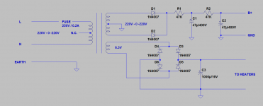
Do you have a diagram of the power supply?
Do you have a diagram of the power supply?
Hi Razorrick1293,
I still could'nt find the time to play with the tone stack (missing some resistor and cap values...). I want to test a 500k pot and tune the circuit accordingly.
Regarding the input CF, I did think of converting this to a gain stage as you suggest, it will be nice to have the option to clip stronger if desired - maybe reach transistor sound ... .
.
My problem with this is that the effect output will be out of phase with 3 inverting gain stages - and I want to keep the CF output. I never design an audio circuit that the output is not in phase with the input.
I attached a schematic of the power supply I use in this circuit.
S.B.D
I still could'nt find the time to play with the tone stack (missing some resistor and cap values...). I want to test a 500k pot and tune the circuit accordingly.
Regarding the input CF, I did think of converting this to a gain stage as you suggest, it will be nice to have the option to clip stronger if desired - maybe reach transistor sound ...
My problem with this is that the effect output will be out of phase with 3 inverting gain stages - and I want to keep the CF output. I never design an audio circuit that the output is not in phase with the input.
I attached a schematic of the power supply I use in this circuit.

S.B.D
It may be overkill, but what about an interstage transformer/output transformer to correct the phase after?
As for hum, I did have a problem with a DC heater supply, the hum did seem to get into the signal path, but adding a 12v zener 10 ohm resistor and 4700uF capacitor helped (12v supply, though a 6v zener, 5 ohm resistor should still be fine). Only problem is that resistor had to have a fairly high power rating, maybe 5 watts. other source of hum could be a ground loop, I usually connect HT ground and heater ground at chasis ground with no problems.
As for hum, I did have a problem with a DC heater supply, the hum did seem to get into the signal path, but adding a 12v zener 10 ohm resistor and 4700uF capacitor helped (12v supply, though a 6v zener, 5 ohm resistor should still be fine). Only problem is that resistor had to have a fairly high power rating, maybe 5 watts. other source of hum could be a ground loop, I usually connect HT ground and heater ground at chasis ground with no problems.
I don't see any smoothing in your heater supply. You appear to have a very large reservoir cap but no subsequent smoothing filter. As it stands I reckon you will get a sawtooth waveform (4 volts peak to peak riding on the DC component) which will be noisier than 6.3 volts AC. Hope I'm wrong.
Cheers
JimG
Cheers
JimG
Last edited:
Yes, the circuit was built and tested. Fuzz effect was very "round", even at full throttle.
For some reason my friend who is a heavy metal player really liked the sound, I thought it needed at least one more gain stage to give the required headroom I like in an effect.
I changed the last stage from a follower to CC for the extra gain I thought needed. It did help, but for some reason I think I would have liked a bit more.
I did have some hum noise, but did not get into trying to insulate the problem.
I will post a picture of the built circuit later on today.
I will post a picture of the built circuit later on today.
Thanks alot! I´ve been getting more and more into tube circuits recently, but I would like to start from a bit less demanding and especially try out some pedal circuits.
- Status
- This old topic is closed. If you want to reopen this topic, contact a moderator using the "Report Post" button.
- Home
- Live Sound
- Instruments and Amps
- Another DIY tube based fuzz
