Hi all.
I am new to this forum and I have what I guess must be a pretty simple problem to start with.
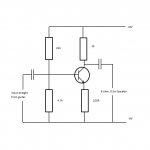
I would like to make a guitar amplifier for my A2 level Product design project and so I thought I would start with a simple transistor amplifier to get things going. Basically, I have tried this a few times and watched videos, read books and seen schematics and I cannot get this circuit to work (see attachment for schematic).
I can hear the interference when I hook up the battery so it all must be connected up, right? But when I plug the guitar in, I get no sound out of the speaker whatsoever. I have tried to follow a schematic I saw on youtube for a transistor preamp where his input was a mic and his output a PA speaker, he ran it through an IC power amp stage though. Do I need to do this to get any sound?
If I need a power amp stage then I would prefer to make it myself out of transistors instead of an IC as I would like understand how it all works, so does anyone have a schematic for a basic power amp stage?
Any help would be appreciated as I don't really know where I am going wrong.
Thanks in advance
Callum
PS, the transistor is a 2N3904 if this matters
I am new to this forum and I have what I guess must be a pretty simple problem to start with.
I would like to make a guitar amplifier for my A2 level Product design project and so I thought I would start with a simple transistor amplifier to get things going. Basically, I have tried this a few times and watched videos, read books and seen schematics and I cannot get this circuit to work (see attachment for schematic).
I can hear the interference when I hook up the battery so it all must be connected up, right? But when I plug the guitar in, I get no sound out of the speaker whatsoever. I have tried to follow a schematic I saw on youtube for a transistor preamp where his input was a mic and his output a PA speaker, he ran it through an IC power amp stage though. Do I need to do this to get any sound?
If I need a power amp stage then I would prefer to make it myself out of transistors instead of an IC as I would like understand how it all works, so does anyone have a schematic for a basic power amp stage?
Any help would be appreciated as I don't really know where I am going wrong.
Thanks in advance
Callum
PS, the transistor is a 2N3904 if this matters
Attachments
First of all,you need more gain. The output signal of a typical guitar is very low,you simply aren't amplifying it enough to be heard.
Second,the circuit you posted is more of a 'low level' amplification stage,it doesn't have the 'grunt' to drive a speaker.You need a power amplifier of some sort,it could be a simple circuit with a couple transistors,and a handful of passives (caps,resistors) or a chip of some sort (LM386 comes to mind).
Second,the circuit you posted is more of a 'low level' amplification stage,it doesn't have the 'grunt' to drive a speaker.You need a power amplifier of some sort,it could be a simple circuit with a couple transistors,and a handful of passives (caps,resistors) or a chip of some sort (LM386 comes to mind).
 This belongs in Instruments & Amplifiers so I will move it there.
The circuit you have provided is just a simple voltage amplifier and cannot drive a speaker directly. A discrete transistor amplifier is a complex undertaking and without some experience you are not too likely to get it working.. A chip based power stage would probably be a better idea.
Hi, thanks for the replies, and thanks for moving it to right place ")
The only reason I wanted to build it using discrete components was to help gain some understanding on how it would work. Is there a basic schematic of an output stage that you know of that I could have a go at? I have struggled to find one.
Thanks again,
Callum
The only reason I wanted to build it using discrete components was to help gain some understanding on how it would work. Is there a basic schematic of an output stage that you know of that I could have a go at? I have struggled to find one.
Thanks again,
Callum
Go to this website: Solid State Guitar Amp Forum | DIY Guitar Amplifiers - Index
Register and then look at the Newcomer's Forum. Read the stickys. They will get you pointed in the right direction.
Register and then look at the Newcomer's Forum. Read the stickys. They will get you pointed in the right direction.
The circuit you've posted has an input impedance of roughly 4k. For a guitar it needs to be more like 400k.
Guitar output varies a lot, but 50-100mV is a reasonable starting point, but only if it connects to a high impedance input - give it 4k and it'll pretty much disappear.
The speaker is very low impedance - 8R (ohms) is common, so it needs a circuit that is better at supplying current. I've never come across a one-transistor practice amp, and I'm old now!
Have a look around and ask again about whatever you find.
Simon is not old , we like to call it experienced. ;-)
Without using SPICE, would you like to go through the ''old school'' way of doing the design analysis? I have not used SPICE yet, I just started texting this year on my cellphone (to my daughter) and I still recall telex machines at my first job. Oh crap!!!
Seriously though maybe a step by step walk through is in order. BTW the 2N3904 really does matter, as it and consequently everything around it will define the operation. It is the active amplifying component .
You should consider the input signal level, and it's source impedance. The output load and what power you need to drive it with. Based on the maximum power dissipation and Hfe of the 2N3904 in class A operation I believe it will not be possible to make the voltage gain AND power gain required to get you to 500 mW at 8 Ohm load .
I would say at least 2 stages required.
I would say at least 2 stages required.
Thanks again for the help I will give that link a look. I spoke to someone who said it needed an output stage and said it could be a push pull stage. Is this a good way forward?
Also, if i increase the resistors on the input side to keep the same bias voltage but increase impedance this should "boost" the signal?
Cheers again,
Callum
Also, if i increase the resistors on the input side to keep the same bias voltage but increase impedance this should "boost" the signal?
Cheers again,
Callum
It can be a push-pull stage, a single-ended one, a bridge, with transistors, FETs or valves, an emitter/source/cathode follower or common-emitter/source/cathode gain stage, class A, AB, D, H, etc. The thing is that you should know basic electronics to be able to design a simple circuit. Calculating in/out impedances is trivial (in an open-loop design), but it takes basic knowledge about how all devices work.
If you don't intend to be an electronics professional, at least study Ohm, Kirchhoff and Thevenin laws, then fundamentals of transistors, then amplification stages, then design of power amplifiers.
Without this, you'll struggle with non-working circuits and we won't even be able to explain why. Hint: your circuit's gain is about -22dB (or, considering the loss by the input Z, about -50dB) - it's an attenuator!
Best regards,
Emerson
Thanks for the hint, I realised there must have been an issue with the gain for me to not be getting any thing out of the speaker. I hadn't realised it would be an attenuator. In the video I watched where this circuit was from, although it was used as a preamp and was followed by a power amp, it worked using all the same values, why does mine have negative gain whereas the other did not?
Thanks again for the response
Callum
Thanks again for the response
Callum
Actually, one more question, How do you work out the input impedance of this circuit? basic I know :L
Cheers
Assume that your input capacitor is large enough that it has very little impedance at frequencies of interest - in this case anything above 82Hz, which is the fundamental of bottom E on a guitar.
Signal current flowing in through that cap sees three branches of circuit in parallel:
Through the 4k7 to ground
Through the 22k to the +ve supply rail, which to signals looks like ground (really).
Into the base of the transistor and then to ground. Because you have an emitter resistance in circuit, of value 100R, and because the transistor has substantial gain the resistance looking into the base terminal will be reasonably high. If the gain, hfe, of the transistor is, for example, 150, the resistance looking into the base of the transistor will be about 15k - the emitter resistance x hfe.
So, calculating 4k7 // 22k // 15k gives 3.08k - a bit lower than I guessed earlier, but I know I tend to over optimism.
The transistor's input impedance has been much increased by the emitter resistance, which provides negative feedback. Some types of feedback reduce input impedance, this one increases it.
Another effect of the negative feedback is that it reduces the gain, and distortion of the amp - with no load attached, the voltage gain of the stage will be roughly 1k / 100R, ie 10. But with an 8R load, voltage gain will fall to about 8R / 100R - 0.08 - not very loud at all!
To get the 0.5W output mentioned earlier, which might surprise you as to how loud it is (only 16 dB quieter than 20W) you need to get 2V RMS across an 8R speaker. Because a guitar signal is quite peaky, that means a peak voltage of something like 8V - or 16V pk-pk (others here will be able to give you a better idea on typical "crest factor" for guitar signal).
That's assuming you don't want to have it distorting at all

I would like to make a guitar amplifier for my A2 level Product design project and so I thought I would start with a simple transistor amplifier to get things going.
From what others have mentioned, you likely get the idea a power amp to drive the speaker is no small chore. Since your projects assumes a guitar and speaker (ie, you're not building those yourself) why not assume a guitar, chip amp, and speaker, and concentrate on making a guitar preamp for your project?The circuit you have provided is just a simple voltage amplifier and cannot drive a speaker directly. A discrete transistor amplifier is a complex undertaking and without some experience you are not too likely to get it working.. A chip based power stage would probably be a better idea.
Alternatively, you could build a "stompbox". There's lots of info out there on those, and uhmmm, if you choose a distortion pedal as a project then many of the "mistakes" you might make in a preamp could be considered one of the "design goals".
Simon also answered the other question, why the circuit worked when used as a preamp followed by a power amp. Why does yours have negative gain whereas the other did not. You get attenuation because your output is connected to a low resistance speaker, but in the example where the power amp is connected it is not loading down the output of your transistor, so signal will have a modest gain.
Your first stage could be modified to get more voltage gain, and then a following stage could take that amplified signal and be designed to drive current into an 8 ohm load at 500 mW. That would be a real basic amp, which is good to start with.
Your first stage could be modified to get more voltage gain, and then a following stage could take that amplified signal and be designed to drive current into an 8 ohm load at 500 mW. That would be a real basic amp, which is good to start with.
Whilst a low wattage power amp doesn't have to be that complex, I'm feeling far too lazy to draw one up right now and I'll therefore throw my weight behind what others are suggesting (more or less):
Build a preamp, that will get your guitar signal up to "line level", for domestic gear that's -10dBV rms, which in volts is 316 mV rms (roughly!).
This would mean that you could test it out with one channel of a not-too-precious solid state hifi amp going into a guitar speaker, or a cheap powered computer speaker - my local computer shop gives those away.
Once you've got your preamp working you could use it to drive a chip amp, like a TDA2030, or just swipe the chip amp and power supply from the computer speakers......gets you a free volume control. If your A level is Product Design, not electronics, I don't see a problem with that at all.
For a guitar to line level preamp the requirements are:
High Z-in (input impedance) - in the range 470k to 1M
20dB gain (ie 10x voltage gain)
Medium Z-out - 600R is quite fine.
Given these, look at this:
Ritter preamp
This circuit uses a fet as the input device, so it has inherently high input impedance. R4, R5 and C1 form a feedback network. The feedback fraction is R4/(R4+R5), so roughly 1/30, and that defines gain as roughly 30x, which is also roughly 30dB. The feedback also lowers the output impedance substantially, but connecting it to a speaker might overload and destroy the output device Q1.
I'd drop R1 down to 1M or even 470k for guitar use, bit less noise with nothing plugged in and easier to get the part.
Only one cap is shown, but you'll need an output coupling cap connected to point A - the value will depend on what impedance it works into. The higher the impedance, the lower the value required. Too low a value will lose you bottom end.
It'd probably be a good idea to have an input coupling cap too, though this can be smaller than the output cap. Say you make R1 470k, and maybe one day you might want to put a bass through it, so let the -3dB low frequency cut-off point be at 20Hz. Then you'd want to choose your input coupling cap to have a reactance of 470k at 20Hz.
The formula for capacitive reactance is "Xc = 1 / (2 x Pi x F x C)" so for -3dB at 20Hz, you want Xc = 470k, swap the equation round and you get:
C = 1 / (2 x Pi x 20 x 470,000)
C = 17nF
next bigger preferred value is 22nF, so use that.
Attachments
Two or three stages
I agree with all of the other posts and I would say that a decent class A-B amp for this purpose would be a three stager. They are fairly simple to build unless you want perfection, which is very hard to achieve. I have built a few of these with great results. You will need some feedback from the output stage to increase gain in the middle section, and you will need to be careful to control oscillations by shunting hf signals to ground with a few small caps, but it can be done. Power supply will have to be robust to really give you any appreciable power. Probably something like + and - 18V and capable of 3 amps max current. Gain staging is really key and the two transistors that will be driving the output pair have to be closely matched, as well as the output pair to a certain degree.
I agree with all of the other posts and I would say that a decent class A-B amp for this purpose would be a three stager. They are fairly simple to build unless you want perfection, which is very hard to achieve. I have built a few of these with great results. You will need some feedback from the output stage to increase gain in the middle section, and you will need to be careful to control oscillations by shunting hf signals to ground with a few small caps, but it can be done. Power supply will have to be robust to really give you any appreciable power. Probably something like + and - 18V and capable of 3 amps max current. Gain staging is really key and the two transistors that will be driving the output pair have to be closely matched, as well as the output pair to a certain degree.
...class A-B amp for this purpose.....will need some feedback from the output stage to increase gain in the middle section.....
?????
Well that certainly saves on tone controls.........you will need to be careful to control oscillations by shunting hf signals to ground with a few small caps......
Not convinced that this is appropriate advice to be offering to this member.
Last edited:
Right I have been trying some stuff out. I have a question now to do with the biasing potential divider circuit. I was trying to bias it with roughly 3V (that's about enough right?) and I used a 22k and a 47k to start with (will alter them for impedence later) wich gave me just less than 3V when I calculated it from a 9V supply, and worked out about right in practice. However, When i added the transistor in, the drop across the lower went to the 0.7Veb and the upper resistor went to the remaining 8V ish. Now I know the transistor set the 0.7V itself, but why does this then alter the divider voltages? I know this is a simple question, but I can't work this one out -_-
Any suggestions would be great,
Cheers, Callum
Any suggestions would be great,
Cheers, Callum
- Status
- This old topic is closed. If you want to reopen this topic, contact a moderator using the "Report Post" button.
- Home
- Live Sound
- Instruments and Amps
- Basic Guitar Transistor Amplifier