Okay, starting to get down to business:
I have stripped the original Fender Transistor Twin chassis,
and spent a week toying with the idea of taking it to a school shop,
and using their bender to fix it up.
Then I just spent ten minutes with a 2x4 and my body weight,
bending it myself on the floor. Not bad.
Now the chassis platform is horizontal,
and the front piece bent at an appropriate angle.
I have yet to saw the over-tall back piece off and re-bolt it,
so that the top-screw lugs line up with the holes in the cabinet.
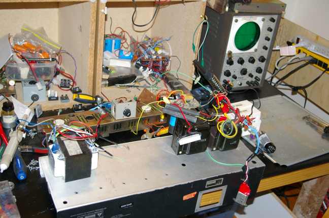
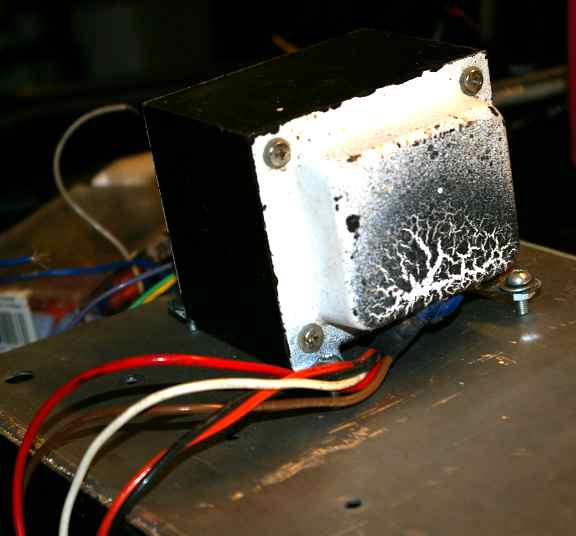
On the left (chassis) is the Boldec 100 watt Ultralinear transformer.
The bells were painted white and fired for coolness (wasted now inside Fender cab).
On the right (chassis) is the HV tranny and the giant (10 H?) choke (bigger than tranny!).
I got this choke I think from Antique Audio 20 years ago as army surplus.
But I thought the only way to get the son started (and off videogames),
was to dump it on his bench, and make a lot of noise.
I built a bench for him under his bed-loft, (see pic),
to encourage him to learn some electronics before his dad goes senile.
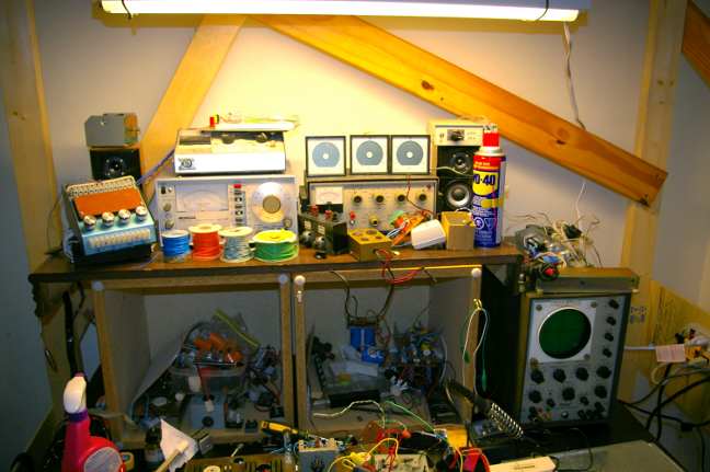
He inherits a lot of cool bits, like that classic EICO oscilloscope,
and custom test-jigs for tube circuits (see upper left).
Some might recognize the ancient Heathkit tone-generator at top right,
and the quickly obsceletized "Distortion Meter" beside it (heh heh).
I have stripped the original Fender Transistor Twin chassis,
and spent a week toying with the idea of taking it to a school shop,
and using their bender to fix it up.
Then I just spent ten minutes with a 2x4 and my body weight,
bending it myself on the floor. Not bad.
Now the chassis platform is horizontal,
and the front piece bent at an appropriate angle.
I have yet to saw the over-tall back piece off and re-bolt it,
so that the top-screw lugs line up with the holes in the cabinet.
On the left (chassis) is the Boldec 100 watt Ultralinear transformer.
The bells were painted white and fired for coolness (wasted now inside Fender cab).
On the right (chassis) is the HV tranny and the giant (10 H?) choke (bigger than tranny!).
I got this choke I think from Antique Audio 20 years ago as army surplus.
But I thought the only way to get the son started (and off videogames),
was to dump it on his bench, and make a lot of noise.
I built a bench for him under his bed-loft, (see pic),
to encourage him to learn some electronics before his dad goes senile.
He inherits a lot of cool bits, like that classic EICO oscilloscope,
and custom test-jigs for tube circuits (see upper left).
Some might recognize the ancient Heathkit tone-generator at top right,
and the quickly obsceletized "Distortion Meter" beside it (heh heh).
Attachments


Last edited:
STARTING!....
Nothing like actually getting down to business!
The chassis needed one more modification.
The extra long back was sawed off, leaving about an inch;
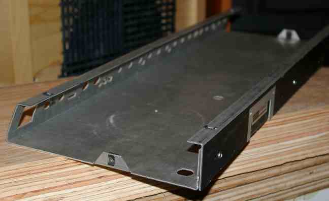
The extra piece was also sawed short, to match the height;
This piece has the bend and chassis-bolt nuts which take the back bolts from above.
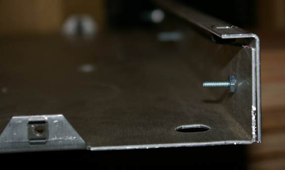
The piece is bolted to the rest of the chassis, to give a strong,
level surface for mounting the transformers and tubes.
As a result, new holes will have to be drilled in sides of the wooden Fender cab, to line up with the side-bolts.
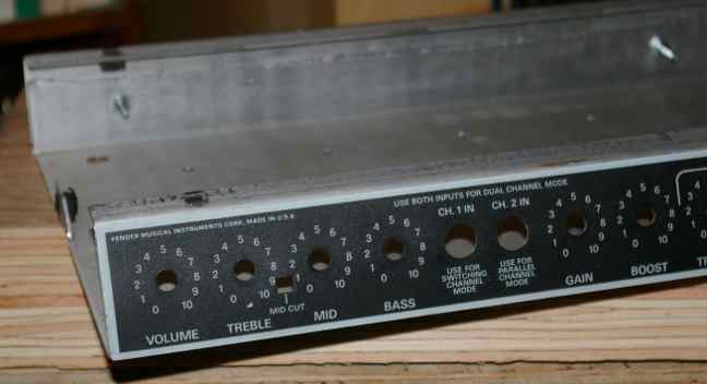
Good news is, most of the front panel can be re-used, the old way,
with chassis-mounted knobs and point-to-point, using a turret board.
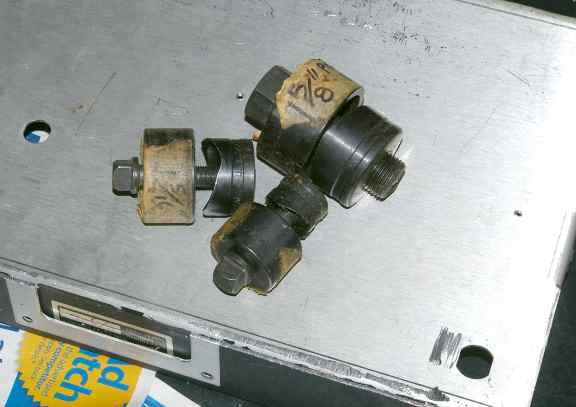
Here's a closeup of the Boltec 100watt UL transformer, with painted bells.
The 'burnt look' was created with a crackle-paint, sprayed lightly over the white.
It gives a hint of the mayhem to come from this best guitar-amp ever built (tribute).
Still pining to use the 814s, but it will have to be on another even more dangerous amp... alas...
Now the fun begins! LAYOUT Time!
Nothing like a new amp project to get you all fired up!

Remember kids! Play Safe!
Nothing like actually getting down to business!
The chassis needed one more modification.
The extra long back was sawed off, leaving about an inch;
The extra piece was also sawed short, to match the height;
This piece has the bend and chassis-bolt nuts which take the back bolts from above.
The piece is bolted to the rest of the chassis, to give a strong,
level surface for mounting the transformers and tubes.
As a result, new holes will have to be drilled in sides of the wooden Fender cab, to line up with the side-bolts.
Good news is, most of the front panel can be re-used, the old way,
with chassis-mounted knobs and point-to-point, using a turret board.
Here's a closeup of the Boltec 100watt UL transformer, with painted bells.
The 'burnt look' was created with a crackle-paint, sprayed lightly over the white.
It gives a hint of the mayhem to come from this best guitar-amp ever built (tribute).
Still pining to use the 814s, but it will have to be on another even more dangerous amp... alas...
Now the fun begins! LAYOUT Time!
Nothing like a new amp project to get you all fired up!
Remember kids! Play Safe!
Attachments


Last edited:
anyone here happen to live in western pennsylvania ?
I can't afford a fender or a bruno or a dumble or even a ceriatone
so Im going to have to do it myself - dangerous -with a lot of help
or else buy a used homemade amp off someone here - safer - but ..
I can't afford a fender or a bruno or a dumble or even a ceriatone
so Im going to have to do it myself - dangerous -with a lot of help
or else buy a used homemade amp off someone here - safer - but ..
Start a new thread with what kind of amp you would eventually have and your price range. I take it from the dangerous part you have no experience, hope your sights are down to earth as with experience you can cut costs or with money you can get by with less experience.
Way back at posts #12 and #13 DF96 stated that ultimately harmonic and intermodulation distortions arise from the same mechanism - non-linearity and Nazaroo wanted an explanation.
I copied this from a post I did to a HiFi Forum. If math gets "on your wick" then skip this post.
Let us consider 2 frequencies in the important 1 to 5 kHz region.
For example use 3kHz and 4kHz:
Most of us understand that superimposing these (mixing in a non- linear system) will produce new frequencies and we often refer to these as sidebands. This is too simplistic.
The maths works like this:
Take 2 sinusoidal signals (well we will use cosine rather than sine to keep the maths simple)
Signal 1 = a1(cos x)
Signal 2 = a2(cos y)
From output = a1 cos(x) + a2 cos👍
Exapanding this and substituting in the trigonometric identity cos(x) + cos👍 = 1/2(cos(x+y) + cos(x-y)) and a lot of tedious algebra later we end up with an expression for:
1) the 2nd order term , For the superposition of 2 signals of x = 3KHz and y = 4kHz then four(4) new frequencies are created, 2 off 2nd harmonic terms and 2 off IM sidebands :
2x = 6kHz , 2nd harmonic of x
2y = 8kHz , 2nd harmonic of y
x + y = 7kHz , IM sideband
x - y = 1kHz , IM sideband
2) The 3rd order term gives six (6) new frequencies. 2 off 3rd harmonics and 4 off IM sidebands
3x= 9kHz , 3rd harmonic of x
3y = 12kHz , 3rd harmonic of y
2x + y = 10kHz , IM Sideband
2x - y = 2kHz , IM Sideband
2y + x = 11kHz , IM sideband
2y - x = 5kHz , IM Sideband
The important thing to note here is that the 2nd harmonic distortion is accompanied by intermodulation product frequencies (sidebands) which are remote from the original frequencies. (1kHz and 7kHz)
The 3rd harmonic is accompanied by more intermodulation products, two(2) of which are very close to the original frequencies. (2kHz and 5kHz)
To exaggerate this (but still a valid example) see what happens with 14kHz and 15kHz
2nd order IM terms are 1kHz and 29kHz (very remote from the original 14 and 15kHz)
3rd order products are 13kHz and 16kHz (very close to the original 14 and 15 kHz)
Higher order terms produce even more IM Sidebands
I might be wrong (because I did'nt extend the algebra past the 2nd and 3rd order terms) but I think the 4th order will produce 6 IM sidebands and the 5th will produce 8 IM Sidebands.
Then consider other sources of a signal with which we can intermodulate.
One of the most important will be the 100Hz (120Hz in the US etc) residual power supply ripple which depending upon the quality of your power supply may well have 200, 300, 400Hz etc. harmonics as well.
At this point the "stray" IM products can run to thousands.
This is why a no feedback single ended triode amp with 2% of 2nd harmonic distortion but no 3rd, 4th, 5th etc can sound stunning and why an SS amp with 0.001% THD distortion which is primarily odd (and high) order distortion can sound awful.
It is also why some amplifiers which sound lovely with folk or jazz music which have a lower number of simultaneous tones (sparse spectra) can sound seriously rubbish when reproducing large choirs and orchestras (many closely spaced tones).
So what can we do about it?
The answer is simply to follow the established "popular wisdom".
1) Keep Power Supplies super clean
2) Don't allow high order harmonic distortion products
3) What harmonic distortion there is should be even (and low order) harmonics ONLY
So here is my theory / explanation / WAG,
In short, higher order harmonic distortions are accompanied by many more Intermodulation Sidebands
Even harmonic distortions are accompanied by IM Sidebands remote from the original frequencies
Odd harmonic distortion are accompanied by IM Sidebands close to the original frequencies (and therefore more objectionable).
Any of this make sense to anyone? The point is that DF96 is right, Harmonic Distortion and Intermodulation Distortion is produced by the same mechanism, the mixing of signals in a non-linear system, You can't have one without also having the other.
Cheers,
Ian
Last edited:
Actually not much about SS amps other thanActually, one of the better explanations of Tube vs. SS sound.
This is why a no feedback single ended triode amp with 2% of 2nd harmonic distortion but no 3rd, 4th, 5th etc can sound stunning and why an SS amp with 0.001% THD distortion which is primarily odd (and high) order distortion can sound awful.
and which does not compare on a level playing field. The SS amp would be implied to have a great deal of NFB otherwise the distortion figure would not be that low. How about a SS amp that has minimal or no NFB as guitar tube amps are designed? Or add a stage or two in a tube amp and then add tons of NFB? Basically mimicking a SS amp, clean up until clipping and then perfect square waves.
The above is more a comparison between even and odd harmonic distortion.
So what can we do about it?
The answer is simply to follow the established "popular wisdom".
1) Keep Power Supplies super clean
2) Don't allow high order harmonic distortion products
3) What harmonic distortion there is should be even (and low order) harmonics ONLY
Clean power supplies, good for either amp.
Higher order harmonics, even or odd, just limit the amount of NFB.
Harmonic distortion should be even? Well that depends on your tastes. Some like it as it thickens up the sound. Others think it makes an amp sound muddy and they prefer odd harmonic distortion in their amp. The old SE to P-P debate. Which is better. Well depends which you like. And then there are the ones that like the higher order harmonics (and associated artifacts that go along with them), those noisy metalheads.
As a general description of a tube amp vs SS guitar amp, I think it to be a suitable explanation to why tube amps are coveted more then SS amps.
He defined the fundamental difference between the sound of the two common types of amps, generally speaking. He implied common configurations.
I have owned many a SS guitar amp, it's a generation thing. No matter how elaborate or powerful, they can be easily relegated to door stop duty when you bring in a "insert any tube amp here" to they party.
Even if a particular tube amp does not suit your taste, you can usually tweak them so they do.
SS, you cannot do much with.
Manufactures have tried very hard, jamming all kinds of DSP effects etc, into amps trying to simulate "tube sound", hurting their image at the same time, inadvertently capitalising on the names that great tube tone built.
I tried to love SS guitar amps, I really did.
Heck I can get a few year old 100w Marshall MG100 or a Fender with DSP for a couple hundred bucks here in Ontario, which incindentally, is less money then a forty plus year old Kay 505 combo with two measly 8" speakers.
Does not bode well for SS amps.
Fender FM212DSP - Barrie Musical Instruments For Sale - Kijiji Barrie Canada.
Kay Amplifier - Model K-505 - Barrie Musical Instruments For Sale - Kijiji Barrie Canada.
Again, other than the one comment comparing a SS amp to a 'a no feedback single ended triode amp' (and how many people like the sound of a SE triode for their guitar?) the post was about two styles of amps, not between SS and tube. If the line with the SS amp is removed the post still is valid to the point the author is making. It is not a SS vs tube debate.
The modeling amps have come a long way in the last five years. Comparing some 'vintage' DSP amps to what manufacturers are doing today and what they will be able to do in the next couple of years will cut into sales of traditional tube and transformer amps. Shoot, I have talked to a number of musicians that are excited over what is being offered for their ipod.
Built an amp in the 70's, no global NFB, barely any local NFB, the power amp with only three gain stages. Rated distortion was 1% at 22W. Sounded great clean or distorted. Mind you with no protection circuitry it did occasionally need a new pair of output transistors. Mind you it was not designed with guitar in mind. Maybe if guitar amps were designed in the same way as tube amps they might have gotten more respect. Build a tube amp with lots of gain and global NFB and it will suck also.
Starting to prep the Chassis!
Here's the latest pics of the build:
These hole-punches are a lifesaver.
They pay for themselves with their first use.
Make sure you use cutting-oil and regular oil on the threads, to keep them sharp.
For accurate hole-placement, small pilot-holes are drilled, then a 3/8" hole for the bolt of the hole-punch.
A half-dozen turns and the piece snaps out, leaving a perfect, finished hole.
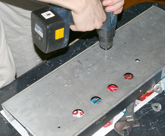
Even if this project is a flop, nothing beats watching the son actually perform useful work!
- and he's gained experience with a new tool, the hole-punch.
Holes for the mounting bolts are also marked and drilled.
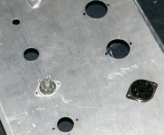
Really nothing should be mounted until the transformers are drilled and bolted on,
but its hard to resist the fun of pre-assembly and a first look:
Here's the latest pics of the build:
These hole-punches are a lifesaver.
They pay for themselves with their first use.
Make sure you use cutting-oil and regular oil on the threads, to keep them sharp.
For accurate hole-placement, small pilot-holes are drilled, then a 3/8" hole for the bolt of the hole-punch.
A half-dozen turns and the piece snaps out, leaving a perfect, finished hole.
Even if this project is a flop, nothing beats watching the son actually perform useful work!
- and he's gained experience with a new tool, the hole-punch.
Holes for the mounting bolts are also marked and drilled.
Really nothing should be mounted until the transformers are drilled and bolted on,
but its hard to resist the fun of pre-assembly and a first look:
Attachments
-
 sneakpeak1.jpg30.6 KB · Views: 388
 -
 Hole-Punches8.jpg51.8 KB · Views: 377
 -
 Hole-Punches7.jpg40.8 KB · Views: 53
 -
 Hole-Punches6.jpg42.8 KB · Views: 55
 -
 Hole-Punches5.jpg56.1 KB · Views: 343
 -
 Hole-Punches4.jpg53.2 KB · Views: 379
 -
 Hole-Punches3.jpg38.9 KB · Views: 330
 -
 Hole-Punches2.jpg35.2 KB · Views: 56
 -
 Hole-Punches1.jpg22.5 KB · Views: 356
Last edited:
Nice, looks great so far. Lots of small holes there. This thread has been dominated by output stage talk, but what's your plan for a pre-amp? Looks pretty substantial! 🙂
Also, do you use any kind of layout software to figure out placement before starting on the chassis? One thing I learned from my first build was that efficient parts placement can be challenging. I rewired my PS three times and the pre-amp twice before I was satisfied, and I'm still not 100% happy with placement in a few sections.
Also, do you use any kind of layout software to figure out placement before starting on the chassis? One thing I learned from my first build was that efficient parts placement can be challenging. I rewired my PS three times and the pre-amp twice before I was satisfied, and I'm still not 100% happy with placement in a few sections.
Nice, looks great so far. Lots of small holes there. This thread has been dominated by output stage talk, but what's your plan for a pre-amp? Looks pretty substantial! 🙂
Well, the basic idea will I hope be to use the front panel almost as it is,
with two basic channels.
In this case, I'm going to try to have one Marshall (overdrive) and one Fender channel (clean).
Each channel will have its own style tone-control, and the Marshall will probably have a distortion/gain plus some switch-in presence or some such.
There will also be a 'Soldano' channel, but it may be switched in/out or subbed for the Fender. Still toying with the problem of 3 channels in a 2-channel frontplate.
Sonically I think we can have everything we want in one amp.
But layout and footswitches might be a compromise.
Nope, I'm not using any layout software or PCB routing aids.Also, do you use any kind of layout software to figure out placement before starting on the chassis? One thing I learned from my first build was that efficient parts placement can be challenging. I rewired my PS three times and the pre-amp twice before I was satisfied, and I'm still not 100% happy with placement in a few sections.

I hope to wire everything point-to-point using some standard turret-boards for the guts, and in part rely on mini-PCBs for the tone-controls/channels.
There isn't that much to a guitar amp,
but the challenge will be educational for my son the assistant.
I don't want him to miss out on the frustration of doing awkward layout.
This is an experience-building project, so he'll have to heatsink or swim.
Basically, all this messing around allows for long conversations and
chances to ask questions about all kinds of circuit issues.
Last edited:
Excellent. The pre-amp sounds quite similar to what I just built. My finished "overdrive" stage is a combination of Marshall/Bogner/Soldano and gives a great range of overdrive up to flat out distortion. The clean channel is very Fenderish also.
For the overlapping channel on the front panel, what Soldano did was use the same tone stack for 2 channels but switched in and out extra gain stages. I've done something similar in mine. I think EVH's 5150 does that also. Might be something you could try.
I used a Traynor Mark-3 combo chassis for mine, and used the original P-to-P rivet board. Definitely a learning experience. For my next design I'll try to use a PCB layout tool to place parts on a P-to-P board to minimise rewiring efforts. I'm sure you'll be able to pass along some frustration to your son during this build. 🙂

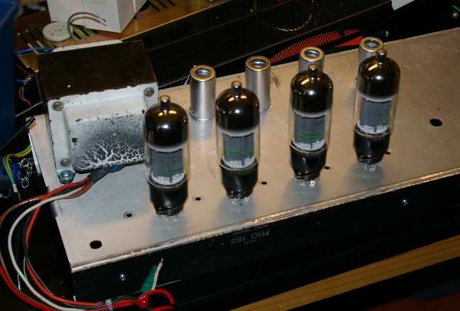
Transformers, Grommet!

Yes, whenever you mount transformers to a chassis, always have plenty of rubber grommets to protect the wiring insulation from abrasion, cuts, and short-circuiting! Especially with high voltage stuff.
First Transformer goes on the Chassis! Output tranny at one end, and power supply trannies and chokes at the other. Orientation aint so critical with this incredibly long chassis.

I always seem to be short of lock-washers. Ideally locknuts would be even better, but hey, we'll be using what is on hand for this economy build. When you run out of washers, you can always use nail-polish to fix nuts from loosening, that are never supposed to come off again. Transformers are one of those parts that should never die!

Here my son is drilling the holes for the massive choke (larger than the Power Tranny!). We had to check for clearance with the speakers in the Fender cab.

After this quick training exercise, my son is now a professional Grommeter!
It first seems impossible to stuff correct-size grommets into the hole, And in the past I've even cut them to assist in tucking them in. But the best tool for this is simply a medium flat-head screwdriver. You have to watch it, so that the rubber isn't penetrated or torn, since that defeats the whole (hole) purpose of protecting the wires from contact with sharp metal edges, and also providing electrical insulation.
Power Plug Innovations:
Next we want to get the power chord installed. But here, instead of the usual fixed line, we want the new 'computer-plug' style. There are several good reasons to go this route:
(1) If the chord is damaged, its an easy replacement, without tools!
(2) You can change the length of the power cord, if you want to add a longer one!
(3) There is built-in powerline filtering in most of these units, which is pretty essential these days with tons of digital broadcast noise all around, (cells, internet etc.) and all kinds of equipment piggy-backing on powerlines (local transmission of security, LANS, even audio!).

But alas, there's a snag! How do you cut a square/rectangular hole with ordinary tools? Sure, of course you can make four or more holes with your drill, dig out the jigsaw and cut out the extra metal, and finish up with some various sized metal files; all a lot of annoying and boring work, which is also time-consuming.
Or you can graduate to
The Nibbler!
When I found out about this tool, I fell in love! It does just what they call it, It nibbles out sheetmetal of almost any thickness or type, and its easy and fast.
Of course the metal handle isn't the most comfortable, but you can either wear a glove, tape on some rubber padding or apply insulating sheaths from a pair of pliers, or just MAN UP and cut the hole! Usually for one or two holes, you don't need to do much except mark out the size and nibble away!

To get started, you just drill a 3/8" or larger pilot hole to work the tool in to where it can start chopping. Be sure to use cutting oil to protect the sharpness of your Nibbler tool, which is going to become your favorite tool for cutting perfect rectangular shapes, refitting new parts which are the wrong size, etc.

Here the son gets an instructional hands-on in Nibbling 101. Soon the AC socket will be ready for power!

A final nostalgic look at today's accomplishments. Time to rest.
I don't want to tucker the boy out.

A few more internals, like caps, a bridge and a power-switch and fuse, and we'll be ready to wire up and test the output stage!
For that, all we need is a good tube-pedal (like one we built earlier) to drive the splitter, Output stage and transformer! Lets rock!
Nazaroo,
For your possible interest.
Here is something I've been meaning to try for a guitar amp but haven't got around to it. Ultralinear plus balanced shunt feedback from the output tube anodes, zero global feedback. I use an enhanced version of this in my HiFi Amps.
That 12K cross connect resistor in the centre of the schemo sets the shunt feedback level.
With EL84 Outputs this worked well with the dominant pole set by the diffamp driving the output tube Miller Capacitance.
With 6V6 The max Rg1 value (100K) causes a bit of a problem in that this also loads the shunt feedback so I added ZVN0545A Mosfet Source followers in between, AC coupled off the diffamp and direct coupled to the output tube grids. That requires a -ve rail on the bottom of the source followers and allows the bias to be applied at the mosfet gates. In the HIFI version I current source load the followers.
I also use a common resistor in the cathodes of the output tubes for some common mode feedback to drop high odd order harmonics and reduce intermodulation distortion. A value of 15% of the single tube cathode bias resistor is what I've found works (e.g. for 6V6 usual cathod ebias resistor is 470 Ohms, I use a common 56 Ohms)
Note: This is not intended as a final working schematic but rather a "sketch" to demonstarate a circuit technique.
Cheers,
Ian
Attachments

Last edited:
If interested the HIFI Amp schematic with this scheme is at post #604 here:
http://www.diyaudio.com/forums/tubes-valves/72536-el84-amp-baby-huey-61.html
http://www.diyaudio.com/forums/tubes-valves/72536-el84-amp-baby-huey-61.html
Nazaroo,
For your possible interest.
Here is something I've been meaning to try for a guitar amp but haven't got around to it. Ultralinear plus balanced shunt feedback from the output tube anodes, zero global feedback. I use an enhanced version of this in my HiFi Amps.
That 12K cross connect resistor in the centre of the schemo sets the shunt feedback level.
With EL84 Outputs this worked well with the dominant pole set by the diffamp driving the output tube Miller Capacitance.
With 6V6 The max Rg1 value (100K) causes a bit of a problem in that this also loads the shunt feedback so I added ZVN0545A Mosfet Source followers in between, AC coupled off the diffamp and direct coupled to the output tube grids. That requires a -ve rail on the bottom of the source followers and allows the bias to be applied at the mosfet gates. In the HIFI version I current source load the followers.
I also use a common resistor in the cathodes of the output tubes for some common mode feedback to drop high odd order harmonics and reduce intermodulation distortion. A value of 15% of the single tube cathode bias resistor is what I've found works (e.g. for 6V6 usual cathod ebias resistor is 470 Ohms, I use a common 56 Ohms)
Note: This is not intended as a final working schematic but rather a "sketch" to demonstarate a circuit technique.
Cheers,
Ian
Thanks Ian:
The diagram as you've sketched it will not feed both sides of the Push-Pull. The lower 12AX7 seems to simply be a grounded grid. Unless its getting a signal from some other source,
it appears to just idle at quiescent current bias setting. (?)
regards,
Nazaroo
The lower 12AX7 seems to simply be a grounded grid. Unless its getting a signal from some other source,
If you visualize the circuit with the two triodes next to each other you can see that the 12AX7 is an LTP with a CCS in the tail. The lower 12AX7 gets its signal from its cathode.
If you visualize the circuit with the two triodes next to each other you can see that the 12AX7 is an LTP with a CCS in the tail. The lower 12AX7 gets its signal from its cathode.
Clever circuit. 😀 The constant current source enforces signal balance (assuming matched load resistors) because the current has to go through one triode or the other. Does the balance pot actually do anything? I would think a trim on one of the 220Ks would do a better job and makeup for any imbalance in the power tubes.
If you visualize the circuit with the two triodes next to each other you can see that the 12AX7 is an LTP with a CCS in the tail. The lower 12AX7 gets its signal from its cathode.
Thanks! I didn't even see the CCS in the tail. I thought that was some kind of measuring point he was taking.
Now I see the feedback.
yes I'm not used to seeing longtailed pairs upside-down...
Doh!
An externally hosted image should be here but it was not working when we last tested it.
- Status
- Not open for further replies.
- Home
- Live Sound
- Instruments and Amps
- 6L6GC / 6BG6 x4 Ultralinear Guitar Amp